29 August 2025

Link-22 12QAM waveform

Fig. 1 - Link-22 transmission

Recently my friend ANgazu from radiofrecuencias.es sent me a great catch of a Link-22 transmission - Figure 1 - recorded at 11128.0 KHz/USB. Identifying the mode (Link-22) is fairly straightforward by examining the bitmap depicting the framing period used by the waveform (Figure 2).
The 112.5 ms duration is typical of the waveforms used by Link-22 and described by STANAG-4539 standard (non-hopping TDMA traffic waveforms). Note that in this case the framing consists of 3 data blocks (DATA) interspersed with three mini-probes (MP) blocks.

Fig. 2 - typical Link-22 framing

Honestly, examining the individual bursts I expected to find QPSK or PSK8 modulations: I was very surprised when the phase plane revealed bursts with QPSK and even 12QAM constellations within the same transmission (Figure 3): clear sign that the header must therefore encode the modulation mode.

Fig. 3 - QPSK and 12QAM constellations

A 12QAM modulation is employed in non-hopping TDMA traffic waveform #13 (Annex G to STANAG-4539):

12QAM is unusual because QAM typically uses powers of 2 (so each symbol cleanly represents an integer number of bits). 12 is not a power of 2, so it cannot map bits directly since log⁡2(12) ≈ 3.585 bits per symbol, which is not an integer.
However, some NATO HF modem implementations of STANAG-4539 use a circular 12QAM layout (which uses two concentric rings) rather than the rectangular one (3x4 grid). Figure 4 shows an approximate layout:
- inner ring 4 points (like QPSK), offset for symmetry
- outer ring 8 points evenly spaced (like 8-PSK)
This design gives a radial + angular separation, making it easier to decode under fading and noise than a rectangular grid. 

Fig. 4 -  circular 12QAM (STANG-4539 style)

This variation of a constellation is not "new" in STANAG-4539 as, for example, the 64-QAM constellation described in paragraph #4.2.2.1.6: "This constellation is a variation on the standard 8 x 8 square constellation, which achieves a better peak-to-average ratio without sacrificing the very good pseudo-Gray code properties of the square constellation".

As seen, with 12QAM circular, the goal is 3.5 bits/symbol (b/sym). There are at least three practical approaches:
1) 4-bit labeling + FEC rate 7/8
2) Multilevel/TCM ( trellis-coded modulation): 3 info bits + 1 structural bit
3) Probabilistic Amplitude Shaping (PAS)
The most common is the 4-bit labeling + FEC rate 7/8:
- assign a 4-bit mapping to the 12 points (16 combos → 12 used, 4 unused).
- apply channel coding with rate R=7/8 (e.g., LDPC or turbo). Net efficiency: 4×7/8=3.5 b/sym.

I can give an Octave example [1] for such method with a 12QAM circular constellation. Since Octave doesn’t have built-in LDPC/RS at hand, the code illustrates it using a simple block code to emulate the R=7/8 effect (i.e., 7 info bits + 1 parity). The principle is the same as using LDPC/Turbo in practice.
What it does:
1. Defines the 12QAM circular constellation (4+8 rings) with 4-bit Gray-like labels.
2. Implements a (7,8) block encoder (simple parity, emulating FEC with rate 7/8).
3. Transmits random data: 7 info bits → +1 parity → 8 coded bits → mapped into 2 QAM symbols.
4. Sends through an AWGN channel.
5. At the receiver: nearest-neighbour detection, recover labels.

Fig. 5 - 4-bit labeling + FEC rate 7/8 simulation

Must be noted that:

* the STANAG-4539 12QAM waveform uses a channel coding with rate R=4/5 and TBCC (Tail-Biting Convolutional Code). Net efficiency: 4×4/5=3.2 b/sym.

* STANAG-4539 is not the same as Link-22, but Link-22 can use STANAG-4539 as one of its underlying HF bearers.

* the Octave code is just an example/simulation just to prove that  ~3.58 bits per symbol fits nicely with the interleaving, coding, and frame structures used in the waveform: I do not know what is the method for the 12QAM used in the analyzed signal.

The choice of 12 points is not arbitrary, it’s a trade-off between spectral efficiency and robustness: it can deliver intermediate data rates where 8-PSK is too low and 16-QAM is too fragile under HF channel conditions. In military waveforms like STANAG-4539, robustness and flexibility matter more than mapping convenience.

 https://disk.yandex.com/d/tMeSf8zZjgdl4w

[1] https://disk.yandex.com/d/kZmCP-fdqtc-cw

22 July 2025

Tunisian Navy using L3Harris Citadel encryption

Prompted by some logs posted on the UDXF group, I started monitoring the USB frequency 12354.4 KHz, operated by the Tunisian Navy (Marine Nationale Tunisienne), hoping to capture something interesting. To be precise, I used the two KiwiSDRs located in central-eastern Italy, operated by IZ6BYY and IK7FMO [1], whom I obviously thank.
The frequency is quite "busy" with 2G-ALE (MS-141) exchanges between tactical callsigns, as RF05 and CT12 in the given sample; once the link is established, message exchange usually occurs via MS-110A using adaptive speed and interleaver (Figure 1). Still in this sample, it is interesting to note that the request to establish a link is transmitted from RF05 (caller node) to CT12 (called node) and after the exchange of messages the link is closed by the called node, as if to signify that there are no other messages to send in the opposite direction (a bit like what happens in 3G-ALE).

Fig. 1

The bistream after demodulation of the three message blocks shows the characteristic 16 bytes start/sync sequence of the L3Harris "Citadel" cipher (Figure 2).

Fig. 2 - Citadel start/sync sequence in the MS-110A demodulated bitstream

After removing the start/sync sequences, the presence of Initialization Vectors (IV) is noted: these are 12-byte/96-bit long, each repeated three times (Figure 3).

79 19 08 E9 61 C4 B1 01 A5 24 9A B7
87 A9 45 4F 28 22 A7 15 33 88 F8 EB
91 1E 71 15 D2 FA FF D3 51 68 6B D0

This is characteristic of the Citadel II "format":
- 16 bytes start/sync sequence 0x1E561E561E561E001A5D1A5D1A5D1A5D (Citadel)
- 12 bytes IV (each 3 times rptd) - OR - 32 bytes IV (2×128 bits parts, each 3 times rptd)     
- ciphertext
- 8 bytes end sequence 0x1E561E561E561E08 (Citadel)


Fig. 3 - 12-bytes/96-bits Initialization Vectors

Some comments

"Citadel II" generally refers to a hardware-based cryptographic solution (cryptographic engine) developed by Harris Corporation (now L3Harris) in 2004, designed for military-grade encryption in "non-Type 1" applications. This means it's approved for secure communications but not for the highest classification levels of US government information (which use "Type 1" ciphers endorsed by the NSA). One might wonder why this encryption is used by a country like Tunisia, which is notoriously not a member of NATO (1): the answer is because it is not a Type 1 device, the Citadel II is approved for export from the United States, making it available to international users.

Citadel II is used in various communication products, including the L3Harris Falcon II range of military radios (such as RF-5800H). Given L3Harris's extensive portfolio and the strong military ties between the US and Tunisia, it is highly probable that the Tunisian Army runs L3Harris equipment, particularly in areas like communications, night vision, and potentially some avionics or electronic systems on US-supplied platforms [2]. However, exact details of specific L3Harris models in Tunisian service are not always publicly disclosed.

The short duration makes one think of "informal messages", perhaps SMTP emails: the encryption unfortunately obscures the data-link protocol sitting at the upper layer, probably STANAG-5066. Considering the use of L3Harris encryption (and probably Falcon radios), one might think that the L3Harris' RF-67x0W Wireless Gateway/Message Terminal is used... but that's just my speculation!

https://disk.yandex.com/d/23rAAmgmk9AiAQ

(1) Since 2015, Tunisia has been granted non-NATO "major ally" status, a status granted by Washington to allied countries that have strategic relations with the American armed forces but are not members of the organization.

[1] https://iz6byy.k1fm.us/  http://ik7fmo.ddns.net:8073/
[2] https://adf-magazine.com/2025/04/tunisian-navy-adds-to-patrol-fleet/


15 July 2025

unid QPSK 2400 Bd Link-22 waveform

A few days ago my friend linkz sent me an interesting recording of a signal spotted on 11166.0 KHz/USB, in addition to the recording he also sent me an excellent "direction finding" work that - in my opinion - allowed a definitive identification of the waveform.
The modulation used is PSK4 at a speed of 2400 Baud (Figure 1).

Fig. 1 - PSK4 2400 Bd modulation

The ACF value is 37.5 ms, which corresponds to a period of 90 symbols (di-bit symbols, given the type of modulation used) or 180 bits (Figure 2): the framing consists of 31 mini-probe known symbols followed by 59 unknown symbols (data block).

Fig. 2 - 90 di-bit symbols framing
 
Regardless of the symbol values (1) the mini-probes appear to be formed using a repeated sequence of 16 symbols, to be precise 16+15, which is similar to that used in the mini-probes of MS-110D (Figs. 3,4) [1].

Fig. 3 - mini-probes symbols of the analyzed PSK4 waveform
Fig. 4 - mini-probes symbols of MS-110D waveform

Direction finding by linkz (TDoA algorithm) returns to Cholet, a French city where Thales has its Telecommunication R&D department (Figure 5).

Fig. 5 - TDoA results (thanks to linkz)

Initially, this clue led me to think of the High Data Rate Single Tone modem built into the Thales TRC-3600/3700 ​​family, which in this example runs the PSK4 waveform. 

Then, my good friend Karapuz commented the post: "Hello, my old friend! Ten years ago I first encountered a similar signal, and it seemed to me then that these packets were used in the TDMA LINK 22 channel"; my friend ANgazu too thinks of a data-link waveform and I have to say they could be right! The ACF value of 37.5 ms is somewhat misleading as it is due to a single "section" of a bit complex waveform: by enlarging the ACF window it is in fact possible to see the classic value of 112.5 ms (270 symbols) which is typical of the Link-22 Media Code Frame (Figure 6).

Fig. 6 - data-link Media Code Frames

The 270 symbols of the Media Code Frame in this sample are arranged according to a QPSK Traffic Waveform consisting of 3 sections with 31/32 symbols mini-probes and 58/59 symbols data blocks (Figs. 7,8). This also explains the mini-probe symbols in Figure 4.

Fig. 7 - the analyzed QPSK data-link  traffic waveform
 

Fig. 8 - the 3 sections of the analyzed QPSK data-link traffic waveform

This is quite unusual since, at least(!) the QPSK traffic waveforms specified in STANAG-4539 Edition 1 (TDMA waveforms, Annex D), have sections with the same number of symbols used for data while the number of symbols used for mini-probes is variable (Figure 9).

Fig. 9 -QPSK traffic waveforms specified STANAG-4539 Edition 1

From web searches, the recent edition of STANAG-4539 (February 22, 2019) provides 18 traffic waveforms, briefly listed in Figure 10, among which there are seven QPSK modulations: unfortunately I don't have this document so I don't know number and framings of the related MP/Data "sections".

Fig. 10 - TDMA STANAG-4539 traffic waveforms

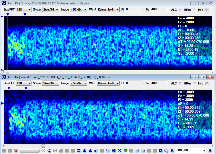
Another interesting point concerns the preamble of the analyzed signal: as can be seen in Figure 11 it uses the same symbols as the Link-22 waveforms. 

Fig. 11 - Link-22 preamble (above) and analyzed signal (below)

However, looking more carefully, the preamble of the Link-22 waveforms (at least of the first three) and that of the signal in question has a duration of about 70 ms and is in contrast with what is specified in Stanag-4539 Annex D #2.3.1, ie "The preamble consists of 203 Symbols transmitted in QPSK at the modulation rate of 2400 baud. The preamble duration is ≈ 84.58 ms": until now I had never noticed this peculiarity.

Fig. 12- preamble durations

The discrepancy between the reported 70 ms and 84.58 ms for the TDMA preamble duration in STANAG-4539 can be attributed to several factors: it's possible that the preamble duration varies slightly between the TDMA waveforms and the ones actually used for Link-22 (!), or even different operational modes within them. Furthermore, there can be different interpretations or implementations of the standard by various manufacturers or research groups, leading to minor variations in reported figures.

 https://disk.yandex.com/d/XiRdODa0hl8j5w

(1) SA is a signal analyzer and not a decoder, therefore its phase-plane demodulator does not sync  any particular protocol. Working with phase keyed signals, the SA phane-plane demodulator produces right interpretations and views (number of phases, angles, modulation speed, carrier frequency,...) but it may return wrong demodulated streams due to the possible phase-offset errors. 

[1] http://i56578-swl.blogspot.com/2024/07/ms-110d-appd-wbhf-transmissions-collins.html

27 June 2025

IPSec (ESP) over HF using STANAG-5066

For a few days I have been monitoring the 20.5 MHz/USB frequency, thanks to the KiwiSDR owned by IZ6BYY [1], recording some transmissions such as the sample in Figure 1, by the way such transmissions are not at all frequent. Data transfer is via the HF waveforms MS-110A and STANAG-4539 (MS-110B App.C), the links are managed by BW5 FLSU (Fast Link SetUp protocol) bursts and therefore everything happens according the "circuit mode service" of  STANAG-4538 (1). 

Fig. 1 - the transmission being analyzed

HF layer
The symbol rate of both waveforms is 2400 Baud, but it was not immediately detectable. In fact, in Figure 2a the automatically detected baud rate value is about 100 Bd (!): a value that is clearly inconsistent. I then used the "modified amplitude detector" function (Figure 2b) which shows a solid continuous line of 2400 Hz and therefore the correct value of 2400 Bd. But the function also reveals faint horizontal lines that "should" represent the baud rate and harmonics and which - unfortunately - should not be there and therefore fool the automatic detection (in PSK modulation the amplitude of the carrier signal remains constant). As a further test I used the automatic detection after the "hard-limited amplitude control" (Figure 2c) and in this case the result is the expected one.

Fig. 2 - Baud rate measurements

Apparently, there is a superimposed 100 Hz signal: according my friend cryptomaster it could be the residual ripple from a full-wave rectifier operating on a 50 Hz AC mains supply, which is then imperfectly filtered by smoothing capacitors.

Fig. 3 - residual ripple from a full-wave rectifier operating on a 50 Hz AC mains supply

The ACF values of MS-110A and STANAG-4539 signals (in the current sample) are respectively ~66.6 ms and ~119.5 ms which - at the speed of 2400 Bd - make 160 symbols frames for MS-110A and 287 symbols frames (256 symbols data block + 31 symbols mini-probe) for STANAG-4539. Actually the length of MS-110A frames is 40 symbols (20 symbols data block + 20 symbols mini-probe) but at slow data rates the length of the scrambler (160 symbols) matches 4 frames and originates the 66.6 ms ACF. Bitmaps and ACFs are shown in Figure 4 (note the four MS-110A frames within the 66.6 ms interval).

Fig. 4 - Bitmaps and ACFs

Figure 5 displays PSK8 constellations that appear "odd" or "twisted" compared to an ideal one. Instead of distinct, equally spaced points on a single circle, we see a slight amplitude variation and a twisted/spiral arrangement of the points. This odd appearance is most likely due to the superposition of the 100 Hz signal, as already highlighted during the baud rate measurement.

Fig. 5 - "twisted" PSK8 constellations

data-link layer
The demodulation of the signals inevitably "suffers" from the non-perfect PSK8 constellations, however it is still possible to analyze the resulting bitstreams and find a 1776-bit period that reveals the use of the STANAG-5066 suite at the data-link layer, presence which is also confirmed by some detections of the 16-bit synchronisation sequences 0x90EB, typical of that Standard.

Fig. 6 - an MS-110A decoded bitstream

The bitstreams have been analyzed using the "STANAG-5066 Dissector" tool [2]; below the traffic-flow output from one of the demodulated bitstreams (S4539.txt) that clearly shows the use of the ARQ DATA-ONLY (simplex) transfer mode; traffic flows from node 001.001.001.101 to node 001.010.010.110 (STANAG-5066 address):


Further "technical" information can be extracted by examining the data transfer frames as for examle the one shown in Figure 7 (frame #26 of 49):

Fig. 7 - a STANAG-5066 frame

As shown, the source and destination Service Access Point Identifiers (SAP ID, equivalent to the “ports” of the TCP protocol) have value 9 (1001 binary) and according to STANAG-5066 they refer to an IP based client/application, more precisely the traffic consists of segmented IPSec (IP Security) packets sent by node 001.001.001.101 to node 001.010.010.110.

user-to-user data
For further analysis of the IP packet we need to extract and edit a "reassembled" C_PDU and then save it as an HEX dump file. Figures 8,9 show an example.

Fig. 8 - an extracted STANAG-5066 C_PDU

We have to remove the first 6 bytes, ie the headers of C (Channel Access Sublayer) and S (Subnetwork Interface Sublayer) Protocol Data Units:
00 07 99 4B 5E 4F
where:
00 C_PDU type (0 = data)
07 S_PDU type (0 = data)
99 S_PDU source & destination SAP IDs (1001 & 1001)
4B 5E 4F S_PDU control and TDD fields
After removing these first 6 bytes you can copy and paste the hexadecimal data and save it to a .txt file, as for example "hex_dump_001.txt":

Fig. 9 - HEX dump file

The HEX dump file can be now analyzed by using the well-known "wireshark" tool [3]: first click "File" -> "Import from Hex Dump", select the file to be imported, set offsets to "none" and Encapsulation Type to "Raw IP" then click Import (Figure 10).

Fig. 10 - wireshark: import from hex dump file

Figure 11 displays the hexadecimal and ASCII representation of the imported IP packet. You can see the bytes that make up the IP header and the subsequent ESP (Encapsulating Security Payload) header and its (encrypted) payload. In summary, this image shows an IPSec (IP Security) ESP packet traveling from the IP addresses 192.168.10.48 to 192.168.1.48. The ESP protocol provides confidentiality, data origin authentication, data integrity, and anti-replay services for IP packets. This type of packet is common in VPN connections or other secure network communications.

Fig. 11 - imported IP packet

The IP header can also be parsed by using the tool CyberChef [4], obviously getting the same results.

Fig. 12 - CyberChef IP parser

Further analysis is not possible since the IP packets payloads are protected by encryption,  however some comments can be added.

The first one concerns the HF waveforms. As seen in Figure 1, HF traffic is conducted in STANAG-4538 "circuit mode". The FLSU Request specifies the traffic waveforms that will be used during the circuit mode service: for example, STANAG-4285 can be specified as the traffic waveform. Once circuit mode begins, any station can initiate transmissions using the specified traffic waveform. Indeed, quoting Annex C to STANAG-4538 "For circuit mode connections, the called station can issue a FLSU Confirm with a different modem parameter (data rate or interleaving), but it shall not change the waveform selection". Well, this is in contrast to what I saw, ie two different waveforms: MS-110A 600bps/S and STANAG-4539 (MS-110B App.C) 4800bps/S, and 9600bps/S also. Although MS-110B superseding MS-110A, Appendix C uses a completely different framing.

Unlike typical IP networks where addresses might be dynamically assigned via DHCP, STANAG-5066 addresses are generally statically configured and are part of the network's design and planning, ie each STANAG-5066 server or device is manually configured with its unique address (Figure 13).

Fig. 13 - manually assignment of a STANAG-5066 address

While STANAG-5066 has its own addressing, it can also provide IP and IPv6 address translation for its subnetwork addresses to allow IP-based applications to communicate over the HF link. In such cases, the mapping between STANAG 5066 addresses and IP addresses would also be part of the static configuration. For example, the sample being analyzed shows the matches:

[STANAG-5066]     [IP]
001.001.001.101  192.168.10.48 source
001.010.010.110  192.168.1.48  dest

Well, about seven years ago (respectively november and october, 2018) I found these matches:
 
[STANAG-5066]     [IP]
001.001.001.101  192.168.2.48  source          
001.003.003.103  192.168.12.48 dest

001.001.001.101  192.168.1.48  source
001.005.005.105  192.168.14.48 dest

Assuming that it is the same HF network(!) and trusting in the goodness of the decoders, you may see that the STANAG-5066 node 001.001.001.101 was always the sender and had 3 different IP mappings (192.168.10.48, 192.168.2.48, 192.168.1.48), as well as the IP node 192.168.1.48 had two different STANAG-5066 mappings (001.010.010.110, 001.001.001.101). Obviously over the time the servers/devices may have changed as well as the related configurations, furthermore only three samples are not so significant.
However, it must be said that ESP protocol may work in "tunnel" and "transport" mode. In tunnel mode, the entire original IP packet (including its original IP header) is encapsulated and becomes the payload of a new, outer IP packet. This means you will see two IP headers:
* an outer IP header that contains the source and destination IP addresses of the IPSec gateways or tunnel endpoints.
* an inner (original) IP header that contains the actual source and destination IP addresses of the end-hosts. This inner header is encrypted along with the original payload(!).
In transport mode, the original IP header is retained. There is only one IP header in the packet. This header contains the source and destination IP addresses of the actual end-hosts communicating.

I can't reliably determine whether these IPSec ESP headers are operating in transport or tunnel mode, thus the above IP addresses may belong to tunnel endpoints (tunnel mode) or directly correspond to the ultimate source and destination hosts (transport mode).
By the way, according to Annex N to STANAG-5066 (Guidance on Address Management in STANAG 5066 Networks) the address range 1.0.0.0-1.255.255.255 is managed by US DoD and includes US Armed Forces and Homeland Security as major S’5066 users.

(1) In the context of STANAG-4538, when we talk about "circuit mode service," we generally refer to establishing a dedicated, continuous connection between two points for the duration of the communication. This is in contrast to the packet mode service, where data is broken into discrete packets and sent independently via xDL protocols.

https://disk.yandex.com/d/LSGj4GzIpjBYOg 
https://disk.yandex.com/d/iZNNGFhziG5opA 

[1] https://iz6byy.k1fm.us/
[2] http://i56578-swl.blogspot.com/2021/02/a-stanag-5066-off-line-dissector.html
[3] https://www.wireshark.org/
[4] https://gchq.github.io/CyberChef/

28 May 2025

Norwegian Navy STANAG 4481-PSK Serial Tone Mode

STANAG 4481 defines the minimum technical standards for Naval shore-to-ship broadcast HF communication. The standard describes three data modem variants, namely the S4481-PSK Serial Tone Mode (STM) providing a BPSK modulated waveform offering data rate of 300 bps coded, the S4481-FSK Single-Channel Two-Tone FSK Mode providing data rates from 50 bps to 600 bps, and the S4481-FSK Multi-Channel (up to 16) Two-Tone FSK Mode providing date rates of 50 bps and 75 bps in a 3 kHz channel. The STANAG 4481-PSK waveform is a Non-Autobaud capable STM (Serial Tone Mode) waveform providing the BPSK modulated 300 bps coded data modem in a 3 kHz channel. The STANAG 4481-PSK modem waveform is identical to the 300 bps long interleaver (10.240 seconds) waveform of STANAG 4285. An example of the S4481-PSK waveform is the fleet brodcast transmitted on 6243.7 KHz/USB by the Royal Norwegian Navy (Figure 1). 

Fig. 1

While the ACF bitmap of Figure 1 clearly shows the classic S-4285 framing, Figure 2 shows the BPSK modulation: notice that some decoders such as Sorcerer and K500 show the constellation related to the type of data modulation (BPSK, QPSK, PSK8) and NOT the "on-air" constellation (usually PSK8).

Fig. 2 - BPSK modulation at 300 bps Long interleaver

User data, at least in this case, are encrypted using KW-46 (or equivalent device) given the presence of the M-sequence generated by the polinomyal x^31 + x^3 +1  (KW-46T uses that M-sequence to synch the KW-46R receive devices).

Fig. 3 - presence of x^31 + x^3 +1 M-sequence

Direction Finding tries (TDoA algorithm) seem to indicate the area of Stavanger as the probable site of the transmitter.

https://disk.yandex.com/d/lo9hwFmEV774Iw