A few days ago my friend linkz
sent me an interesting recording of a signal spotted on 11166.0
KHz/USB, in addition to the recording he also sent me an excellent
"direction finding" work that - in my opinion - allowed a definitive
identification of the waveform.
The modulation used is PSK4 at a speed of 2400 Baud (Figure 1).
 |
| Fig. 1 - PSK4 2400 Bd modulation |
The ACF value is 37.5 ms, which corresponds to a period of 90 symbols (di-bit symbols, given the type of modulation used) or 180 bits (Figure 2): the framing consists of 31 mini-probe known symbols followed by 59 unknown symbols (data block).
 |
| Fig. 2 - 90 di-bit symbols framing |
 |
| Fig. 3 - mini-probes symbols of the analyzed PSK4 waveform |
 |
| Fig. 4 - mini-probes symbols of MS-110D waveform |
Direction finding by linkz (TDoA algorithm) returns to Cholet, a French city where Thales has its Telecommunication R&D department (Figure 5).
 |
| Fig. 5 - TDoA results (thanks to linkz) |
Then, my good friend Karapuz commented the post: "Hello,
my old friend! Ten years ago I first encountered a similar signal, and
it seemed to me then that these packets were used in the TDMA LINK 22
channel"; my friend ANgazu too thinks of a data-link waveform and I have to say they could be right! The ACF value of
37.5 ms is somewhat misleading as it is due to a single "section" of a
bit complex waveform: by enlarging the ACF window it is in fact possible
to see the classic value of 112.5 ms (270 symbols) which is typical of
the Link-22 Media Code Frame (Figure 6).
 |
| Fig. 6 - data-link Media Code Frames |
The
270 symbols of the Media Code Frame in this sample are arranged
according to a QPSK Traffic Waveform consisting of 3 sections with 31/32
symbols mini-probes and 58/59 symbols data blocks (Figs. 7,8). This also explains the mini-probe symbols in Figure 4.
 |
| Fig. 7 - the analyzed QPSK data-link traffic waveform |
 |
| Fig. 8 - the 3 sections of the analyzed QPSK data-link traffic waveform |
This is quite unusual since, at least(!) the QPSK traffic waveforms specified
in STANAG-4539 Edition 1 (TDMA waveforms, Annex D), have sections with the same
number of symbols used for data while the number of symbols used for mini-probes
is variable (Figure 9).
 |
| Fig. 9 -QPSK traffic waveforms specified STANAG-4539 Edition 1 |
From web searches, the recent edition of STANAG-4539 (February 22, 2019) provides 18 traffic waveforms, briefly listed in Figure 10, among which there are seven QPSK modulations: unfortunately I don't have this document so I don't know number and framings of the related MP/Data "sections".
 |
| Fig. 10 - TDMA STANAG-4539 traffic waveforms |
Another interesting point concerns the preamble of the analyzed signal: as can be seen in Figure 11 it uses the same symbols as the Link-22 waveforms.

Fig. 11 - Link-22 preamble (above) and analyzed signal (below)
However, looking more carefully, the preamble of the Link-22 waveforms (at least of the first three) and that of the signal in question has a duration of about 70 ms and is in contrast with what is specified in Stanag-4539 Annex D #2.3.1, ie "The preamble consists of 203 Symbols transmitted in QPSK at the modulation rate of 2400 baud. The preamble duration is ≈ 84.58 ms": until now I had never noticed this peculiarity.
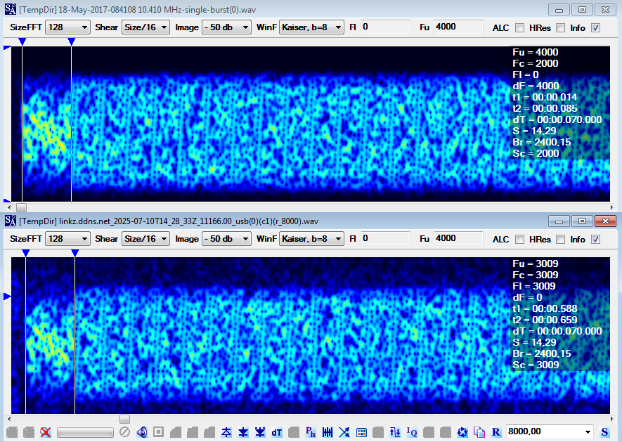
Fig. 12- preamble durations
The discrepancy between the reported 70 ms and 84.58 ms for the TDMA preamble duration in STANAG-4539 can be attributed to several factors: it's possible that the preamble duration varies slightly between the TDMA waveforms and the ones actually used for Link-22 (!), or even different operational modes within them. Furthermore, there can be different interpretations or implementations of the standard by various manufacturers or research groups, leading to minor variations in reported figures.
https://disk.yandex.com/d/XiRdODa0hl8j5w
(1) SA is a signal analyzer and not a decoder, therefore its phase-plane demodulator does not sync any particular protocol. Working with phase keyed signals, the SA phane-plane demodulator produces right interpretations and views (number of phases, angles, modulation speed, carrier frequency,...) but it may return wrong demodulated streams due to the possible phase-offset errors.
[1] http://i56578-swl.blogspot.com/2024/07/ms-110d-appd-wbhf-transmissions-collins.html
No comments:
Post a Comment