Showing posts with label STANAG-4539. Show all posts

15 February 2026

S-4481/S-4539 clear-text messages sent using RapidM modem (BRE1TA tests?)

The purpose of this post is to report test transmissions heard on 6963.0 kHz USB and logged during the first week of February by both Kosmod (who sent them to me for analysis) and ANgazu (whose signal was reported by KA0KA and published on the radiofrecuencias.es forum [1]). I don’t claim much credit in this post, other than confirming previous analyses and contributing further insights.
Transmissions continued for several days without interruption, almost entirely using the STANAG-4539 (MS-110B App.C) waveform. One of Kosmod’s recordings was particularly notable, as the STANAG-4539 signal was preceded by a STANAG-4481 transmission at 75 Bd/850 Hz (Figure 1). The mode switch lasted roughly 640 ms.

Fig. 1 - STANAG-4481/STANAG-4539 switch

According to STANAG-4539, each data frame contains a 256-symbol data block followed by a 31-symbol mini-probe of known data, for a total of 287 symbols per frame (119.57 ms @ 2400 symbols/s). Every 72 frames, a 72-symbol subset of the initial preamble is reinserted to aid late acquisition (1) (Figure 2).

Fig. 2 - STANAG-4539 framing

The data rate is 9600 bps, and the modulation used to achieve it is QAM-64. According to STANAG-4539, §4.2.2.1.6, “This [QAM-64] constellation is a variation on the standard 8 × 8 square constellation, which achieves a better peak-to-average ratio without sacrificing the very good pseudo-Gray code properties of the square constellation” (Figure 3).

Fig. 3 - STANAG-4539 constellations

In both cases (STANAG 4481 and STANAG 4539), the modulations are asynchronous and employ an 8N1 framing format, as shown in Figure 4.

Fig. 4 - STANAG-4481 and STANAG-4539 demodulated bitstreams

The transmitted messages are 8-bit ASCII clear text and consist of repeated instances of the same sentence, differing only in the message sequence number:
[binary header][message sequence number][text] 
The portions of the demodulated bitstreams presented below were obtained from two different recordings (header is omitted):

[STANAG-4481]
...
000013 Rapid Mobile HF & V/UHF Data Modem internally generated test message.
000014 Rapid Mobile HF & V/UHF Data Modem internally generated test message.
000015 Rapid Mobile HF & V/UHF Data Modem internally generated test message.
000016 Rapid Mobile HF & V/UHF Data Modem internally generated test message.
...


[STANAG-4539]
...
004820 Rapid Mobile HF & V/UHF Data Modem internally generated test message.
004821 Rapid Mobile HF & V/UHF Data Modem internally generated test message.
004822 Rapid Mobile HF & V/UHF Data Modem internally generated test message.
...

The message sequence numbering is likely continuous across the transition from STANAG-4481 to STANAG-4539 (Figure 2); however, this assessment cannot be confirmed due to unreliable demodulation of the initial segment of STANAG-4539.

Despite the modem-generated test traffic, the end-to-end efficiency η from payload to physical layer transmission can be evaluated for this STANAG-4539 waveform. As shown, the 9600 bps input uses asynchronous framing with 1 start bit and 1 stop bit, meaning each byte is transmitted as 10 bits of which only 8 carry payload; the symbol rate of 2400 Bd employing QAM-64 modulation (6 bits per symbol) results in a gross channel bit rate of 14400 bps. So:

- net useful payload = 9600 × (8/10) = 7680 bps
- transport efficiency relative to 14400 bps rate:
η = 7680/14400 ≈ 0.533  i.e., an effective efficiency of approximately 53.3%

overhead breakdown:
20% from serial framing (start/stop bits)
~26.7% due to physical-layer mechanisms such as FEC, preambles, and synchronization (S-4539) (2)

It's evident that a RapidM (Rapid Mobile) modem is being used that is capable of producing its own test traffic without needing an external server or another device to send data. This feature is often known as loopback testing, built-in test signal generation, or self-test mode.
Unfortunately, there is no publicly documented statement that a specific RapidM modem model generates its own test message, manufacturers often keep detailed test features in restricted datasheets. However, RM2, RM5, RM8, and RM10 RapidM modems all support STANAG -4539 and STANAG- 4481. RM2/RM5 are narrowband tactical modems (up to 9600  bps) with built-in test/loopback capabilities. RM8 is a strategic/naval narrowband modem supporting 9600–19200  bps and 2G/3G ALE, also capable of self-generated test traffic. RM10 adds wideband HF (3–24 kHz) while retaining narrowband 4539/4481 support [2].

Regarding the transmitting antenna’s location, both Kosmod and ANgazu performed direction finding using the TDoA (Time Difference of Arrival) algorithm, and both results pointed to an area near Casteau-Mons in Belgium, very close to NATO’s SHAPE headquarters (3)[3].

Fig. 5 - Direction Finding results

Direction Finding results may further substantiate ANgazu’s hypothesis that the signals could represent test transmissions associated with the NATO BRE1TA (BRASS Enhancement 1 Technical Architecture) program. BRE1TA constitutes a major architectural evolution of the NATO BRASS (Broadcast and Ship-to-Shore) HF communications system, designed to integrate advanced narrowband and wideband HF waveforms, higher spectral efficiency, improved link robustness, and IP-based data services. 

Several hours of monitoring on 6063 kHz USB over the past few days yielded only occasional short STANAG-4285 300 bps long-interleaver transmissions encrypted with KG-84. Reception was further limited by sporadic fading during the morning sessions.

https://disk.yandex.com/d/CXaz6URgUh-3zg

(1) In Change Notice 1 of MIL-STD-110C (January 2012), the United States Department of Defense removed a sentence stating that a “reinserted preamble facilitates acquisition (or re-acquisition) of an ongoing broadcast transmission.”  The reason was that the sentence referred to a feature that had become obsolete. Keeping it in the standard could have caused confusion by implying support for a legacy broadcast capability that was no longer part of the modem design. 

2) The relationship between the nominal user data rate of 9600 bit/s and the over-the-air symbol rate of 2400 baud for the STANAG-4539 QAM-64 waveform is as follows:
- the waveform employs a symbol rate of 2400 symbols per second with 64-QAM modulation, corresponding to 6 bits per symbol. This results in a gross channel bit rate of 14400 bit/s;
- the application of forward error correction (FEC) with coding rate R = 3/4 to a user data rate of 9600 bit/s produces a coded bit rate of 12800 bit/s;
- the remaining capacity of 1600 bit/s (14400-12800), representing the difference between the gross channel bit rate and the coded bit rate, is allocated to waveform overhead. This overhead includes, but is not limited to, miniprobes and periodic preamble reinsertion required to support synchronization and channel estimation functions. 

Figure below shows an example; the 1-second interval is chosen for ease of presentation.

over-the-air symbols/bits in a 1 second interval (STANAG-4539)

(3) The Supreme Headquarters Allied Powers Europe (SHAPE) is the headquarters of NATO's Allied Operations Command (ACO), located in Casteau, near Mons, Belgium. It is responsible for the planning and execution of all NATO military operations worldwide.

[1] https://www.radiofrecuencias.es/viewtopic.php?p=12527#p12527
[2] https://www.rapidm.com/
[3] https://shape.nato.int/

29 August 2025

Link-22 12QAM waveform

Fig. 1 - Link-22 transmission

Recently my friend ANgazu from radiofrecuencias.es sent me a great catch of a Link-22 transmission - Figure 1 - recorded at 11128.0 KHz/USB. Identifying the mode (Link-22) is fairly straightforward by examining the bitmap depicting the framing period used by the waveform (Figure 2).
The 112.5 ms duration is typical of the waveforms used by Link-22 and described by STANAG-4539 standard (non-hopping TDMA traffic waveforms). Note that in this case the framing consists of 3 data blocks (DATA) interspersed with three mini-probes (MP) blocks.

Fig. 2 - typical Link-22 framing

Honestly, examining the individual bursts I expected to find QPSK or PSK8 modulations: I was very surprised when the phase plane revealed bursts with QPSK and even 12QAM constellations within the same transmission (Figure 3): clear sign that the header must therefore encode the modulation mode.

Fig. 3 - QPSK and 12QAM constellations

A 12QAM modulation is employed in non-hopping TDMA traffic waveform #13 (Annex G to STANAG-4539):

12QAM is unusual because QAM typically uses powers of 2 (so each symbol cleanly represents an integer number of bits). 12 is not a power of 2, so it cannot map bits directly since log⁡2(12) ≈ 3.585 bits per symbol, which is not an integer.
However, some NATO HF modem implementations of STANAG-4539 use a circular 12QAM layout (which uses two concentric rings) rather than the rectangular one (3x4 grid). Figure 4 shows an approximate layout:
- inner ring 4 points (like QPSK), offset for symmetry
- outer ring 8 points evenly spaced (like 8-PSK)
This design gives a radial + angular separation, making it easier to decode under fading and noise than a rectangular grid. 

Fig. 4 -  circular 12QAM (STANG-4539 style)

This variation of a constellation is not "new" in STANAG-4539 as, for example, the 64-QAM constellation described in paragraph #4.2.2.1.6: "This constellation is a variation on the standard 8 x 8 square constellation, which achieves a better peak-to-average ratio without sacrificing the very good pseudo-Gray code properties of the square constellation".

As seen, with 12QAM circular, the goal is 3.5 bits/symbol (b/sym). There are at least three practical approaches:
1) 4-bit labeling + FEC rate 7/8
2) Multilevel/TCM ( trellis-coded modulation): 3 info bits + 1 structural bit
3) Probabilistic Amplitude Shaping (PAS)
The most common is the 4-bit labeling + FEC rate 7/8:
- assign a 4-bit mapping to the 12 points (16 combos → 12 used, 4 unused).
- apply channel coding with rate R=7/8 (e.g., LDPC or turbo). Net efficiency: 4×7/8=3.5 b/sym.

I can give an Octave example [1] for such method with a 12QAM circular constellation. Since Octave doesn’t have built-in LDPC/RS at hand, the code illustrates it using a simple block code to emulate the R=7/8 effect (i.e., 7 info bits + 1 parity). The principle is the same as using LDPC/Turbo in practice.
What it does:
1. Defines the 12QAM circular constellation (4+8 rings) with 4-bit Gray-like labels.
2. Implements a (7,8) block encoder (simple parity, emulating FEC with rate 7/8).
3. Transmits random data: 7 info bits → +1 parity → 8 coded bits → mapped into 2 QAM symbols.
4. Sends through an AWGN channel.
5. At the receiver: nearest-neighbour detection, recover labels.

Fig. 5 - 4-bit labeling + FEC rate 7/8 simulation

Must be noted that:

* the STANAG-4539 12QAM waveform uses a channel coding with rate R=4/5 and TBCC (Tail-Biting Convolutional Code). Net efficiency: 4×4/5=3.2 b/sym.

* STANAG-4539 is not the same as Link-22, but Link-22 can use STANAG-4539 as one of its underlying HF bearers.

* the Octave code is just an example/simulation just to prove that  ~3.58 bits per symbol fits nicely with the interleaving, coding, and frame structures used in the waveform: I do not know what is the method for the 12QAM used in the analyzed signal.

The choice of 12 points is not arbitrary, it’s a trade-off between spectral efficiency and robustness: it can deliver intermediate data rates where 8-PSK is too low and 16-QAM is too fragile under HF channel conditions. In military waveforms like STANAG-4539, robustness and flexibility matter more than mapping convenience.

 https://disk.yandex.com/d/tMeSf8zZjgdl4w

[1] https://disk.yandex.com/d/kZmCP-fdqtc-cw

15 July 2025

unid QPSK 2400 Bd Link-22 waveform

A few days ago my friend linkz sent me an interesting recording of a signal spotted on 11166.0 KHz/USB, in addition to the recording he also sent me an excellent "direction finding" work that - in my opinion - allowed a definitive identification of the waveform.
The modulation used is PSK4 at a speed of 2400 Baud (Figure 1).

Fig. 1 - PSK4 2400 Bd modulation

The ACF value is 37.5 ms, which corresponds to a period of 90 symbols (di-bit symbols, given the type of modulation used) or 180 bits (Figure 2): the framing consists of 31 mini-probe known symbols followed by 59 unknown symbols (data block).

Fig. 2 - 90 di-bit symbols framing
 
Regardless of the symbol values (1) the mini-probes appear to be formed using a repeated sequence of 16 symbols, to be precise 16+15, which is similar to that used in the mini-probes of MS-110D (Figs. 3,4) [1].

Fig. 3 - mini-probes symbols of the analyzed PSK4 waveform
Fig. 4 - mini-probes symbols of MS-110D waveform

Direction finding by linkz (TDoA algorithm) returns to Cholet, a French city where Thales has its Telecommunication R&D department (Figure 5).

Fig. 5 - TDoA results (thanks to linkz)

Initially, this clue led me to think of the High Data Rate Single Tone modem built into the Thales TRC-3600/3700 ​​family, which in this example runs the PSK4 waveform. 

Then, my good friend Karapuz commented the post: "Hello, my old friend! Ten years ago I first encountered a similar signal, and it seemed to me then that these packets were used in the TDMA LINK 22 channel"; my friend ANgazu too thinks of a data-link waveform and I have to say they could be right! The ACF value of 37.5 ms is somewhat misleading as it is due to a single "section" of a bit complex waveform: by enlarging the ACF window it is in fact possible to see the classic value of 112.5 ms (270 symbols) which is typical of the Link-22 Media Code Frame (Figure 6).

Fig. 6 - data-link Media Code Frames

The 270 symbols of the Media Code Frame in this sample are arranged according to a QPSK Traffic Waveform consisting of 3 sections with 31/32 symbols mini-probes and 58/59 symbols data blocks (Figs. 7,8). This also explains the mini-probe symbols in Figure 4.

Fig. 7 - the analyzed QPSK data-link  traffic waveform
 

Fig. 8 - the 3 sections of the analyzed QPSK data-link traffic waveform

This is quite unusual since, at least(!) the QPSK traffic waveforms specified in STANAG-4539 Edition 1 (TDMA waveforms, Annex D), have sections with the same number of symbols used for data while the number of symbols used for mini-probes is variable (Figure 9).

Fig. 9 -QPSK traffic waveforms specified STANAG-4539 Edition 1

From web searches, the recent edition of STANAG-4539 (February 22, 2019) provides 18 traffic waveforms, briefly listed in Figure 10, among which there are seven QPSK modulations: unfortunately I don't have this document so I don't know number and framings of the related MP/Data "sections".

Fig. 10 - TDMA STANAG-4539 traffic waveforms

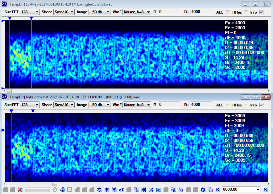
Another interesting point concerns the preamble of the analyzed signal: as can be seen in Figure 11 it uses the same symbols as the Link-22 waveforms. 

Fig. 11 - Link-22 preamble (above) and analyzed signal (below)

However, looking more carefully, the preamble of the Link-22 waveforms (at least of the first three) and that of the signal in question has a duration of about 70 ms and is in contrast with what is specified in Stanag-4539 Annex D #2.3.1, ie "The preamble consists of 203 Symbols transmitted in QPSK at the modulation rate of 2400 baud. The preamble duration is ≈ 84.58 ms": until now I had never noticed this peculiarity.

Fig. 12- preamble durations

The discrepancy between the reported 70 ms and 84.58 ms for the TDMA preamble duration in STANAG-4539 can be attributed to several factors: it's possible that the preamble duration varies slightly between the TDMA waveforms and the ones actually used for Link-22 (!), or even different operational modes within them. Furthermore, there can be different interpretations or implementations of the standard by various manufacturers or research groups, leading to minor variations in reported figures.

 https://disk.yandex.com/d/XiRdODa0hl8j5w

(1) SA is a signal analyzer and not a decoder, therefore its phase-plane demodulator does not sync  any particular protocol. Working with phase keyed signals, the SA phane-plane demodulator produces right interpretations and views (number of phases, angles, modulation speed, carrier frequency,...) but it may return wrong demodulated streams due to the possible phase-offset errors. 

[1] http://i56578-swl.blogspot.com/2024/07/ms-110d-appd-wbhf-transmissions-collins.html

27 January 2024

QPSK (Link-22) & PSK8 (unid) bursts

Since some days on 7907.0 KHz/USB, starting in the morning, it's possible to hear long sessions of 2400Bd burst signals which use different modulations and ways. Signal "A" in Figure 1 consists of 4-segment bursts, each segment lasting about 420 ms.

Fig. 1

Modulation used is PSK8 at the rate of 2400Bd. The demodulated bitstream has a period length of 18 bits (6 PSK8 symbols, Figure 2) that can be reduced to 3 bits or even 2 bits if the "1s" column is removed.

Fig. 2 - demodulated bitstream of a PSK8 burst

Signal "B" in Figure 3 is the same as the above but in this case two station are involved, as it's easy to figure out looking at the different strengths of the bursts and their fading patterns. The "2-stations" mode starts randomly after a while but w/out a sort of schedule: in my opinion the time-slot paradigma (or Time Division Multiple Access mode, TDMA) is used (1).

Fig. 3

Signal "C" (Figure 4) use QPSK modulation instead (again 2400Bd) and 550 ms bursts with a "duty cycle" of 50%. 

Fig. 4

The demodulated bitstreams have a period length of 540 bits (270 PSK4 symbols, Figure 5) with a clearly visible framing consisting of 8 sections "Data-MiniProbe" of different durations. The 270-symbol frames and the durations of the eight "Data-MP" sections are the same of the STANAG-4539 TDMA waveform WF2 (see Table I), thus the recording "C" is definitely a Link-22 transmission (2).

Table I

Fig. 5

All my direction finding tries (TDoA algorithm with 5 receivers!) point to an area near Nuremberg (Nürnberg), Germany. Probably it's the USAG (U.S. Army Garrison) Ansbach base which is located in northern Bavaria, approximately 40 kilometers southwest of Nuremberg [1].

Fig. 6 - Direction Finding tries

For what concerns the PSK8 bursts, bitstreams and TDMA mode make me think about a Tactical Data Link (TDL), even if the analyzed waveforms do not match the standards Link-11 or Link-22 (atleast the ones I know). Anyway, given the lack of other information, it cannot be ruled out that it could be telemetry signals.

Monitoring has been made thanks to KiwiSDRs of OE3AKB (Landersdorf, AUSTRIA) e OZ1BFM (Vejby, Denmark) [2][3].

https://disk.yandex.com/d/b04EpZUQIO5GIw

(1) In TDMA mode each user is allowed to transmit only within specified time intervals named as "Time Slots" so that different users transmit in differents time slots.

(2) #2.3.2 Media Code Frame structure, Annex D to STANAG-4539 

[1] https://installations.militaryonesource.mil/.../ansbach-united-states-army-garrison
[2] http://oe3akb.ddns.net:8073/
[3] http://oz1bfm.proxy.kiwisdr.com:8073/


26 October 2023

NILE/Link-22, likely QAM traffic waveforms

Two NILE/Link-22 close channels recorded this morning (26th October) on 14.656 KHz and 14.659 KHz using a remote AirSpy server located in Romania [1], traffic in the two channels flowed in alternating mode.

Fig. 1 - NILE/Link-22 transmissions

Link-22 use the TDMA (Time Division Multiple Access) waveforms, as for STANAG-4539 Annex D: modulation technique consists of phase shifting of a 00 Hz sub-carrier and speed of 2400 baud. In TDMA mode each user is allowed to transmit only within specified time intervals named as "Time Slots" so that different users transmit in differents time slots (1). According to S-4539 Annex D, a TDMA slot is the high level structure in which information will be transmitted/received and it is composed of a Preamble, a certain number of Media Code Frames and a Guard Time.


A Media Code Frame is composed of 270 symbols to be transmitted at the modulation rate of 2400 baud and using different Traffic Waveforms and modulations. Each Traffic Waveform is composed of a sequence of different Data blocks and Mini Probe (MP) blocks: the Data block contains coded information symbols and the MP block contains known training symbols to be used by the equaliser. The Mini Probes symbols, prior to scrambling, are all symbols number 0. Since the 270 symbols of the Media Code Frame, regardless the used Traffic Waveform, it's ACF has a value of 112.5 ms.
Figures 2 & 3 show that the two Link-22 channels use two different Traffic Waveforms to arrange the 112.5-ms/270-symbol length of the media code frame; also notice that they use the same time slot duration since both send 15 media code frames per time slot.

Fig. 2 

Fig. 3

Given the poor SNR of the signals I was unable to find clear constellations and therefore identify the type of the Traffic Waveforms that were used; attempts suggest the use of QAM modulations (Figure 4).

Fig. 4

Unfortunately I don't have the 2019 edition of Stanag-4539 but only the first edition dated 2005 which specified only three waveforms (QPSK & PSK8): as you may see, the framings resulting in figures 2,3 do not correspond.


https://disk.yandex.com/d/xPhBz07F5Oh5tg

(1) separation among users is performed in the time domain https://en.wikipedia.org/wiki/Time-division_multiple_access

[1] sdr://79.118.167.161:5556 

7 July 2021

unid STANAG-4539 3200bps bursts

Interesting and unid STANAG-4539 bursts recorded on 5270.0 KHz/usb. The user data rate is 3200 bps and is obtained using QPSK modulation, short interleaver is used. Notice that the quadrature phase-shift keying constellation is scrambled to appear, on-air, as a PSK8 constellation. The bursts have a duration of 1350 ms, each transports nine 256-symbols data blocks, and do not seem to obey to a particular timing.

Fig. 1 - S4539 3200bps waveform

The bitstreams after demodulation have a common preamble consisting of three components (Figure 2):

a) idle sequences of '0's and '1's (depending on the polarity of the receive modem)
b) initial 334-bit (frame sync?) sequence
c) 128-bit length Initialization Vector, three times repeated (3x128-bit)

encrypted data block follow.

Fig. 2 - COMSEC preambles

The most interesting component is the 334-bit sync sequence that has a particular 24-bit period and - as a mere attempt - I found that it could be generated by the polynomial x^21+x^10+1.

Fig. 3 - 334-bit sync sequence

By the way, MIL 188-220D describes the three components which compose the initial COMSEC preamble: the Bit Synchronization subfield or the Phasing subfield (it may consists of a string of alternating ones and zeros), the Frame Synchronization subfield, and the Initialization Vector subfield (Figure 4); it must be said, anyway, that the Bit Synchronization patterns do not match. Notice that Figure D3 illustrates the case where the Robust Frame Synchronization is not used (see 188-220D #D.5.2.2)

Fig. 4

User, purposes of the transmissions, and Tx location(s) are unidentified; the only thing I can add is that the better reception is possible by using receivers located in the north Europe countries: by the way, I used two KiwiSDRs located in Denmark [1] and Norway [2].

https://disk.yandex.com/d/KgUT7aaESDD6hA

[1] http://85.191.81.117:8073/
[2] http://kiwi.wlansupport.no:8073/

17 April 2021

unid secondary protocol

Recently I ran across on several transmissions in the 5 MHz band (also available on a secondary basis for amateur use) consisting of STANAG-4538 point-to-point circuit mode service with 188-110A and STANAG-4539 as traffic waveforms at several speeds. The transmissions are receivable in Northern Europe with a good SNR, especially using the KiwiSDR receiver at OZ1AEF (Skanderborg, Denmark): they are very frequent, of short duration, and occur on at least a half dozen different channels between 5300 and 5400 KHz USB. Given their unpredictability (time/channel) and their duration, a Direction Finding is very difficult, at least with the means at my disposal.  


The excellent SNR allows demodulations without many errors and therefore the possibility of examining and comparing the obtained bitstreams: to be honest, I expected to find a known data-link protocol or at least sequences attributable to some encryption technique (known or not )... but that's not what exactly happened.  Although the ACF doesn't produce results, comparing various demodulations it turns out that all the bitstreams exhibit the same initial 16-bit sequence 11110000100111010111 (0x90EB). 
 
Fig. 1

By syncing the bitstreams on the two sequences, interesting results are obtained: in particular,  patterns that have a fairly well-defined structure in the first 192 bit  (Figure 3).

Fig. 3 - bitstreams synched on 0000100111010111 sequence (first 192 bit) 
 

One could argue that the 16-bit sequence (LSB)0000100111010111(MSB) is the binary equivalent for 0x90EB, ie the sync sequence of STANAG-5066 frames: unfortunately, the following bytes do not match the Data Transfer Sublayer headers, ie the (supposed) fields do not contain data that make sense (EOT, size of address,...).

https://disk.yandex.com/d/qPt2CXC2x76yfg (wav)

https://disk.yandex.com/d/8tn5OrrXlsuL4A (streams)


4 October 2019

NILE/Link-22 168-bit packets (STANAG-4539 TDMA WF2 waveform)

(updated)
For background it might be helpful to read the posts:
TDMA waveforms, Annex D to STANAG4539 
NILE/Link-22 traffic waveform #2 

In the sample being analyzed, the 270 symbols of the Media Code Frames are transmitted at the modulation rate of 2400 baud and follow the QPSK waveform #2 structure that consists of 8 sections with 18 symbols DATA blocks and 15/16 symbols Mini Probes (MP). 

Fig. 1
Table 1 - Modulation Type and Contents for WF2 (Annex D to STANAG-4539 Edition 1)
The number of Media Code Frames to be transmitted per TDMA slot (i.e. a burst) is specified to the modem by the Link-22 System Network Controller (SNC) based on the Data Link Processor (DLP) supplied parameters and hence the size of the number of network packets that shall be used to accomodate the incoming messages.
In this sample each slot is composed of 9 frames each consisting of 168 bits, as specified in Annex D to S4539 (WF2, RS(36,21) in Table 2) and in a Link-22 publication [1] about the minimun size of a network packet (Table 3). Both the Tables refer to HF Fixed Frequency operations (HF FF).

Table 2 - Waveform Summary (Annex D to STANAG-4539 Edition 1)
Table 3 - Link-22 transmission media types (Understanding voice and data link networking [1])
My friend YING coded a sofware to demodulate and decode Link-22 WF2 samples, he kindly sent me a decoded bitstream and gave me some interesting insights: "I also found that (1) most of waveforms meet the RS(36,21), and seems only a little meets the RS(36,30). (2) all the RS decode bits have the byte 0x0B, which is strange" YING says. Indeed, the bitstream has a very interesting pattern (Fig. 2):

Fig. 2- Link-22 decoded stream (168 bits window)
Even more interesting is the hex representation of a single TDMA slot (9 frames) which exhibits features that are not immediately visible at glance in the bitwise representation:

48-bit fields A and A' has the same contents

4-bit fields marked with "*" differ by 0x8
4-bit fields B and B' has the same contents
4-bit fields C and C' has the same contents

- fixed position of the byte 0x0B (as noted by YING)

         A          B             C          A'         B'   C'
 ----------------- *-             -  ----------------- *-    -
 29 FB 1F A9 44 20 A9 C4 9F 96 C4 1F 29 FB 1F A9 44 20 29 0B 1E
 5F CA E1 95 32 11 57 F8 E9 A7 3A 23 5F CA E1 95 32 11 D7 0B 22
 DB A6 9E 99 B6 7D 28 F4 6D CB 45 2F DB A6 9E 99 B6 7D A8 0B 2E
 8C F5 65 E3 E1 2E D3 8E 3A 98 BE 55 8C F5 65 E3 E1 2E 53 0B 54
 22 D4 3F A6 4F 0F 89 CB 94 B9 E4 10 22 D4 3F A6 4F 0F 09 0B 10
 3E CB AC CD 53 10 1A A0 88 A6 77 7B 3E CB AC CD 53 10 9A 0B 7A
 7A A0 B0 DD 17 7B 06 B0 CC CD 6B 6B 7A A0 B0 DD 17 7B 86 0B 6A
 FE F5 04 CE 93 2E B2 A3 48 98 DF 78 FE F5 04 CE 93 2E 32 0B 78
 3C B6 D0 A7 51 6D 66 CA 8A DB 0B 11 3C B6 D0 A7 51 6D E6 0B 10

(each 168-bit row is a 112.5ms Media Code Frame)


Quoting STANAG-5522 TACTICAL MESSAGE CONSTRUCTION: "Link-22 tactical messages are functionally oriented, variable length strings of an integer number of up to eight 72-bit words (Tactical Message Words).  These 72 bits words are formatted into network packets by the System Network Controller.  Parity bits for Forward Error Correction are applied at the Network Packet level". This means that what we see are network packets and not solely Link-22 messages.
If it's easy to verify that the number of Media Code Frames carried by a burst is 9, it is however difficult to establish the number of 72-bit words and hence the possible format of the message (from 72 up to 576 bits long). Help in this direction comes from the hex stream. Link-22 traffic is usually encrypted by KIV-21/LLC, a stand-alone in-line network crypto device: the stream, however, does not seem encrypted. Looking at the Link-22 Functional Diagram in Fig. 3, the NETSEC FUNCTION block provides akso an unencrypted interface for the transfer of control and status information (C&S):

Fig. 3 - Link-22 Functional Diagram (STANAG-5522 Edition 1)
Thus, an easy conclusion could be that each 112.5ms frame transports two unencrypted Link-22 words (144 bits) plus 24 bits low-level overhead (Error Detection And Correction (EDAC) bits, flags, spare, etc.?). Table 4 confirms my guess:

Table 4 - Waveforms, RS code rate, and Link-22 words
("Technical handbook for radio monitoring HF", Roland Proesch)
Table 5 is the result of a my comparison between Tables 2 and 4: it turns out that a fixed length of 24 bits is always appended. Curiously, this length is 1/3 (24 bits) of the length of a Link-22 word (unfortunately Table 5 is limited to the waveforms WF1-3 since the new annexes to STANAG-4539 are not at my disposal).

TABLE 5
Just as a test I tried a quite raw suddivision in which the fields that have the same values occupy the same positions within two Link-22 words:

 71                      00           71                       00
 --------------------------            --------------------------   
 29 FB 1F A9 44 20 A9 C4 9F  96 C4 1F  29 FB 1F A9 44 20 29 0B 1E
 5F CA E1 95 32 11 57 F8 E9  A7 3A 23  5F CA E1 95 32 11 D7 0B 22
 DB A6 9E 99 B6 7D 28 F4 6D  CB 45 2F  DB A6 9E 99 B6 7D A8 0B 2E
 8C F5 65 E3 E1 2E D3 8E 3A  98 BE 55  8C F5 65 E3 E1 2E 53 0B 54
 22 D4 3F A6 4F 0F 89 CB 94  B9 E4 10  22 D4 3F A6 4F 0F 09 0B 10
 3E CB AC CD 53 10 1A A0 88  A6 77 7B  3E CB AC CD 53 10 9A 0B 7A
 7A A0 B0 DD 17 7B 06 B0 CC  CD 6B 6B  7A A0 B0 DD 17 7B 86 0B 6A
 FE F5 04 CE 93 2E B2 A3 48  98 DF 78  FE F5 04 CE 93 2E 32 0B 78
 3C B6 D0 A7 51 6D 66 CA 8A  DB 0B 11  3C B6 D0 A7 51 6D E6 0B 10

However, the byte-oriented view is misleading and actually makes a poor sense since the words and overheads are structured in bits rather than in bytes. (1)
Moreover, it should be noted that we do not have to deal with clean and reassembled packets but just with decoded on-air symbols. I mean that Link-22 network packets may undergo a fragmentation and probably that is what we are facing: indeed, the autocorrelation of the bitstream exhibits a strong value of 96 bits i.e. just one 72-bit word plus 24-bit overhead (Fig. 4). 

Fig. 4 - TDMA slot autocorrelation
Summary
Based on the above, we think that the analyzed sample consists of unencrypted Link-22 F-series C&S messages, although it could also be 70-bit Link-16 messages which are encapsulated in Link-22 structure. At least for waveforms WF1-3, the network controller always adds 24 bits overheads to the incoming Link-22 messages: we need more time to study this block and find the CRC sequence (if any).

24-bit overheads update (October, 4)
The packets after WF2 RS(36,21) decoding consist of 144 bits which are needed to convey two words, plus 24 bits of overhead. Referring to Figure 3, these packets are somewhere inside the Signal Processing Controller block which performs modulation and demodulation, as well as error detection and correction (EDAC). Well, I think the 24 bits overhead partly consist of CRC bits (I do not think a CRC-24 is used).
As STANAG-5522 seems to suggest, Link-22 applies the CRC to the whole of words of each packet (i.e. not to each word). Although actually I do not know neither the length of the CRC neither its positioning inside a packet, most likely Link-22 uses a CRC-16 parity check. The remaining 8 bits could be used to accomodate the needed bits for the packet header and maybe one or more additional spare bits so to match the numbers of the k-bytes used for Reed Solomon encodings.
Indeed, as you can see in table 5, the value of k in RS(n,k) codings is 3 bytes longer than the room needed to convey the words. According to the waveform being used, SPC will package words, header, and CRC bits into a packet of the appropriate number of bits for modulation and transmission. 
(to be continued)

(1)
The data fields used are of 3 types: binary, logical, and numeric. Binary data fields are one bit fields containing a 0 or 1. The meaning of the value of each field is described in the applicable message definition. Logical data fields are multibit fields whose bit configurations represent logical values as described in the applicable message definition. Numeric data fields are multibit fields whose bit configurations represent actual numeric values. Spare fields are included in some messages. When transmitted, these spare fields will be encoded as zero and shall not be processed upon receipt.