31 December 2021

UK DHFCS St.Eval running the Aus 600Bd/850 FSK waveform

Since a few days ago, approximately from the fourth week of December, on 2815.0 KHz (CF) it's possible to receive a strong and continuous 600Bd/850 FSK transmissions which is likely a fleet broadcast (figure 1).

Fig. 1 - 600Bd/850 FSK waveform

Transmissions are secured by KW-46 crypto devices; indeed, as per STANAG-5065, the 7-bit stream is featured by the M-sequence generated by the polynomial x^31+x^3+1 which substitues the stop-bits and acts as sync sequence for the receive KW-46, the remaining 6 bits are encrypted (figure 2).

Fig. 2 - KW-46 sync sequence

Regarding these broadcasts, there are two aspects that are worth underlining: 

a) that particular FSK format (600 Baud, 850 Hz shift) was recently adopted by the Australian Defense Force (ADF) MHFCS (1) to replace their previous ISB system. As a further confirm, these signals exhibit a quite unique sign when inspecting their harmonics: the presence of several spectral lines in the 7^ power, as shown in figure 3. It's to notice the lack of the "paired" 50Bd/850 FSK channel (operating 4 KHz above);

Fig. 3 - the harmonics in 7^ power

b) that channel (2815.0 KHz CF) belongs to the UK Defence High Frequency Communications System (DHFCS) and until a few before it was possible to receive on that frequency the ordinary fleet broadcast consisting of STANAG-4481F (75Bd/850 FSK) transmissions encrypted with KG-84/KIV-7 devices.

Given the probable location of the transmitter, I chose to run the Direction Finding tool using 'test' receivers near England; furthermore, given the frequency, I preferred to carry out the tests (TDoA method) in the morning to avoid wave reflections and therefore try to obtain results based as much as possible on direct wave reception. As expected, all the several DF runs point to an area close to the UK RAF site of St.Eval in Cornwall (figure 4): an HF transmitting station, with Penhale Sands as the associated receiving station, which is operated by Babock Defence Communication (as part of the Defence High Frequency Communications System) on behalf of the Ministry of Defense.

Fig. 4 - Direction Finding (TDoA) results

Therefore it can be said that the previous NATO STANAG-4481F (KG-84 secured) broadcast has now been replaced by the ADF 600Bd/850 (KW-46 secured) broadcast, both transmitted from the UK DHFCS site in St.Eval: that's a really curious "paradigm shift" in terms of FSK waveform and encryption (75Bd/850 → 600Bd/850, KG-84 → KW-46), don't know if it has something to do with the trilateral security partnership between Australia, the United Kingdom, and the United States (AUKUS), or it's some training/exercise. Anyway, I checked the FSK frequencies of DHFCS (at least the ones I know) to understand if this mode was also used in other channels but it was not successful. Frequency monitoring will give us more information.


 https://disk.yandex.com/d/BXLEeV10tp7gKg

1) Australian Defence Force (ADF) Modernised High Frequency Communications System (MHFCS) is a managed, long-range strategic communications system that enables the secure exchange of information, such as voice, e-mail, facsimile, interactive data and organizational messages, between fixed and mobile stations using one integrated system. 

23 December 2021

unid 500Bd/1000 FSK ARQ network

This is an interesting "Akula-like" FSK waveform spotted by my friend cryptomaster on 7370 KHz/usb (41 mt broadcast band!), the signals are keyed at the speed of 500 Baud with frequency spacing of 1000 Hz. The recorded session consists of messages (the longer segments) followed by short ACKs which are sent back from apparently two correspondents; ACKs partially overlap each other and sometimes they seem even superimposed (figure 1).  

Fig. 1 - FSK 500Bd/1000

The raw decoded streams of the messages show a 24-bit period length with a solid column of "1"s (or "0"s), the presence of the initial "0011" sequences in place of "01" clearly indicates that the signal is differential encoded (figure 2). Notice the violation of the bit reversal structure (a "1" is inserted instead of a "0") when the system transits to the traffic condition.

Fig. 2 - raw and differential decoded signal

After differential decoding, I found consistent matches for the scrambler described by the polynomial x^12+x^10+x^9+x^3+1 (or its equivalent x^12+x^9+x^3+x^2+1): after its removal, a common "area" of (at least) 253 bits emerges immediately after reversals (figure 3): most likely that's the preamble section which therefore consists of a 253-bit pseudo-random sequence (PRBS) which is part of the 4096 bit M-sequence generated by the aforementioned polynomial.  

Fig. 3

Removing the initial reversals from the differential decoded bitstreams, we are able to get and analyze either the data blocks and the preamble sequences: as expected, the latters are the same (figure 4).

Fig. 4 - 253-bit pseudo-random sequence used in the sent messages

The data blocks are even-parity checked (figure 5) and consist of 24-bit codewords each consisting of 23-bit length data sequence followed by one parity bit. Since the use of a single parity bit can't correct any error, my idea is that they could use a kind of (24,k) code with 24-k parity bits (EDAC bits). The identification of which particular code is used is not easy, it must be taken into account that the parity bits maybe dispersed in the codeword and the possible use of the bit-inversion technique as well as the order in which data and EDAC bits are arranged into the codewords.

Fig. 5
 
The identification of which particular code is used is not easy, it must be taken into account that the parity bits maybe dispersed in the codeword and the possible use of the bit-inversion technique as well as the order in which data and EDAC bits are arranged into the codewords. I checked the Golay(24,12) and Hamming(24,18) codes but unsuccessfully.
 
The ‘ACK’  packets are also differentially encoded. Their preamble is a pseudo-random sequence which is part of the same M-sequence generated by the aforementioned polynomial x^12+x^10+x^9+x^3+1; in this case, the minimum "common" area found after descrambling has a length of 251 bits (figure 6).


Looking at figure 7, the variation of the length of the initial bit reversals (260 and 980 ms) of both message and ‘ACK’ packets suggest that the messages are sent by separate modems. Indeed, listening to the recording it is obvious, that (at least) three different stations are present and that they seem to operate in half-duplex mode with one station at a time sending messages, and one or two stations responding, sometimes on top of each other.
Also notice in figure 7 the lack of ‘ACK’ after message B. This might indicate the deployment of a stop-and-wait ARQ mode, ie A packet is repeated until an acknowledgement is received. However, the decoded succeeding message C is not identical to message B.

Fig. 7

Please, also notice that the partial collisions of the ‘ACKs’ occur when the message transmitting modem is the one with a long run of bit reversals. Such a partial collision is much more evident in figure 8 where the existence of two slave modems can be clearly distinguished. This could indicate that this station is the master station of the network.  

Fig. 8

Due to the partial collisions, the shorter ‘ACKs’ as expected only exhibits part of the preamble sequence (figure 9):

Fig. 9
 
The hypothesis of overlapping modems is also supported by the examination of the SNRs of the two signals, as shown in figure 10 (thanks to "Audacity" free software [1]).
 
Fig. 10
 

Differential demodulation in chronological order of the recorded ‘ACKs’, does not offer much additional information other than a very varied 48-bit format (see figure 11). In the figure the lengths of the data sections are unequal. That format is due to the fact, that I somewhat arbitrarily used the beginning of the trailing bit reversal ("01") sequence (if any) as a delimiter; there is no obvious evidence of parity bits nor of particular patterns. Bit reversals and preambles have been removed.


So, judging from the observations described above, it seems that we are facing a more complex scenario than the simple two nodes in half-duplex, ie a network consisting of multiple (at least three) stations that exchange messages in ARQ mode, sometimes one sender and two correspondents at time, and sometimes just one correspondent.

With a cautious approach, I could imagine three reasons for the collisions:
a) They might be due to the fact that the correspondents sometimes are unable to hear each other and thus 'think' that it's their turn to transmit. However, one would expect a network with a master station broadcasting and several slave outstations responding to have a centrally determined schedule with fixed intervals preventing outstations from interfering with each other, somewhat like Link-11, or, even better, a GPS-synched network like STANAG-4538

b) It is also possible that the reason for these phenomena are seen as collisions are due to the location of the intercepting station in relation to the location of the network stations being monitored, which could give rise to differences in the propagation time at the interception site and the intended recipient

c) And, finally, the short ‘ACKs’ might be a combination of acknowledgement and request to transmit or changeover commands ('you next')
 
Further investigations are in progress... and thanks to my friend Nicola for the editing.

15 December 2021

Chinese PSK2 2400Bd serial waveform

This is my follow-up to an interesting post discussed on the radioscanner.ru forum about a PSK2 transmission of the Chinese Navy and started by my friend KarapuZ [1].  The raw demodulated stream consists of an initial preamble followed by data block consisting of a serie of 16-bit structures which are delimited by solid columns of "1"s or "0"s; the  period is calculated in 3072, 2048, and 1024 bit (128-bit length is due to the preamble sequences): the percentage values in figure 1 indicate respectively  the average ACF value for the given period, followed by the real value of the ACF for that period). Although the value of 1024 bit is the third positive result, both ACF and CCF indicate this as the most likely, being the other two integer multiples of it (x3, x2): this way, the stream consists of 64 "channels", each consisting of 16 bit.

Fig. 1

As noted by my friend Cryptomaster, the 15-bit information between the solid columns is parity-checked; thus, assuming the parity bit is added, as usual, after the data string, each row could consist of 14 bits for data (x) + 1 parity bit (p) + 1 delimiter bit (d): xxxxxxxxxxxxxxpd.
 
I proceeded to the parity check of some channels taking into account all sixteen bits, given that: 
 
* the add of a column of "0"s does not affect the parity checksum of the channel (even or odd); 
* the add of a column of "1"s switches the parity checksum (from even to odd and vice-versa).

The results for some channels are shown in figure 2, it's to be noticed that the max number of dd/even parity parity matches occurs after shifted the stream (offset >1). Looking at the sequence of the parity checksums of the examined channels, and considering the previous assumptions, we get an apparently random alternation of odd and even parity checksums. 

Fig. 2

After the differential decoding, the channels' "delimiters" disappear, so I tried to get the differential decoding of each channel resorting to some sort of workaround: basically I cut off the 16-bit channels from the plain decoding and then I differential decoded each of them. Yes I know, it's an hazard as it assumes that the channels are individually differential encoded (in real-world the first bit of the n channel depends on the last bit of the n-1 channel) ... however, in that way, the channels are all odd-parity checked and perfectly aligned (figure 3).

Fig. 3 - channels after their individual differential decoding

Since the use of a single parity bit cannot correct any errors, and given the amount of data transmitted, my idea is that they could use a kind of (16,k) coding with the overall parity bit added at the end of the codeword.

For what concerns the preamble sequence, it can be successfully descrambled using the polynomial x^18+x^13+x^11+x^5+x^2+1 (figure 4): it means that the preamble actually consists of a 128-bit pseudo-random sequence (PRBS) which is part of the M-sequence generated by the aforedmentioned polynomial.

Fig. 4 - 128-bit PRBS used as preamble

https://disk.yandex.com/d/b8oQdmhTJcJhPg

[1] http://www.radioscanner.ru/forum/topic40144-14.html#msg1540957 

11 December 2021

CIS 2400Bd serial bursts

 Just to point out some differences bewteen these two types of CIS bursts (figure 1) :

* the ones sent in group or in front of the OFDM-121
* the ones sent individually or before Serdolik MFSK/OFDM 

Fig. 1
 
Both the bursts are 2400 Baud keyed and have the same 20ms ACF value as well as - likely - the used modulation, although their constellations and state transitions are not much help in identifying the type of modulation (figure 2): most likely PSK2 in preambles and reinserted probes. The number of the transmitted frames is different, 33 Vs 22, but since they have the same 48-symbol length framing (same ACF) their duration differs (about 760 and 476 ms).

Fig. 2

For what concerns the structure of the frames, the classical method can be misleading, showing two different structures consisting of 33 unknown symbols + 15 known symbols for a type of burst and 32 unknown symbols + 16 known symbols for the other (figure 3a); the plain raster method anyway shows the same 32 + 16 framing for both the burst (figure 3b).
 
Fig. 3a

Fig. 3b

Given the different systems in which these bursts are used, and also the modalities of their transmission (isolated, in group or in front of OFDM), I think they also have different purposes and functionalities.

https://disk.yandex.com/d/wLHbQn4iGgZeZA

6 December 2021

THALES Skymaster, "skyhopper" mode


This is a fairly comprehensive list of the ALE waveforms provided by Thales' Systeme 3000 Series Skymaster and Skyhopper Modes, a set of procedures and adaptive waveforms that allow to offer reliable and real-time optimized links even in degraded ionospheric conditions of the HF channel. All the signals, kindly sent me by my friend ANgazu, belong to the same session, even if the recording is edited in the time axis. These Thales proprietary waveforms are used in TRC-3500/TRC-3600 and TRC-3700 series transceivers.

The first two parts are the Skyhopper mode, an intelligent frequency hopping and automatic hop band selection; the signals consist of a series of 40 ms MFSK-8 125 Bd bursts (figure 1) and 50 ms GMSK / OQPSK 200 Bd bursts (figure 2). It's interesting to notice that the MFSK-8 burst actually use 5-out-of-8 tones of the Skymaster ALE waveform (see the comparison in Figure 1 below).
 
Fig. 1 - MFSK-8 125Bd/250 (actually 5-out-of-8 tones)

The following 50 ms bursts, below in figure 2, are of difficult analysis given their duration and the used modulation, friends of  radioscanner suggest OQPSK modulation.

Fig. 2

The third part is the "classic" GMSK/OQPSK 2000 Bd & MFSK-8 125 Bd/250 part, see figure 3.
 
Fig. 3

The initial GMSK/OQPSK part has a 50 ms ACF that corresponds to a 100-bit frame: the waveform is similar to Harris RF-5800 selective call (figure 4).
 
Fig. 4 - framing' comparison of Thales (up) and Harris (down)  ALE


3 December 2021

Notes about Akula (v. 291121b)

My friend Nicola, with whom we often collaborate and whom I thank here, has been studying Akula's code for several months now and recently sent me a paper related to his work: I am very happy to publish the (current) results of his analysis, soliciting readers to express their views and comments. 

1. Introduction
Akula (the formal designation is not known) is a communication system used by the Russian navy. Originally Akula was designed as a high speed morse based communication system for submarines to avoid HF direction finding. Various sources set the maximum on-air time for these transmissions to 0.72 seconds. It was not until the USA started deploying the gigantic Wullenweber direction finding antennas that it became possible to triangulate (or multi-angulate) these transmissions.
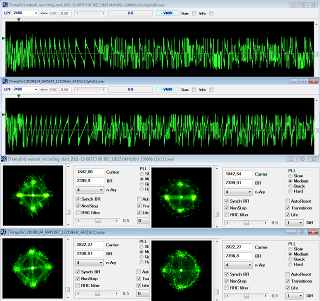
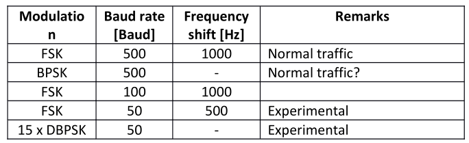
Today’s Akula normally uses FSK at 500 Baud and a 6-bit alphabet for surface communication links. A
variant called Akula II is a DBPSK burst modem for the use among other in submarine communications.
Other variants have been observed, see Table I below.

Table I

Messages intercepted have mostly consisted of encrypted streams, however messages consisting of five
figure groups have also been observed.

2. Alphabet
2.1. Preliminary approaches

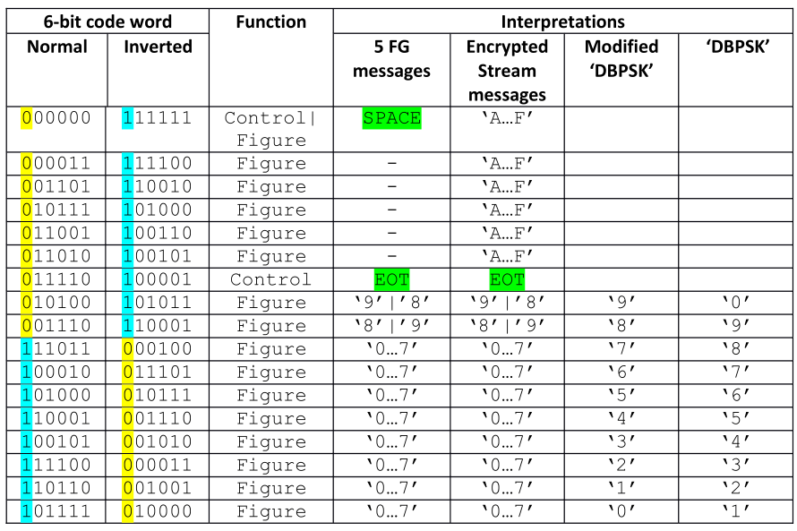
Akula utilizes a 6-bit alphabet. Until now 17 different code words have been identified. What the characters represent seems to depend on the message payload format, i.e. five-figure groups or encrypted stream. Ten characters represent the figures from 1 to 9, 6 represent the hex numbers A to F,one represents both a decimal number and SPACE and one is a control character, EOT. 

The only code words determined with certainty when these notes were begun, were ’Separator’ (000000 or 11111) and ‘EOT’ (011110 or 011110) marked in green. The codewords representing a decimal figure (0-9) have been determined from a message containing only five figure-groups, but the actual value assigned to a character was not known. However, another interpretation has been done, based on a message perceived as a test transmission in DBPSK modulation.

Table II below shows the 6-bit alphabet in use for Akula consolidating the information available at the time these notes were begun. Characters with the MSB bit set to ‘1’ in normal condition or ‘0’ in inverted condition are part of the number range 0-7, whereas the ones with the MSB bit set to ‘0’ in normal condition or ‘1’ in inverted condition are either within the range 8 – F or is a control character.

Table II - Akula 6-bit alphabet
 

Figure 1 (below, to the left) shows an interpretation, based on the assumption that the message represents the sequence “1 2 3 4 5 6 7 8 9 0” and that the group ‘4443’ in fact represents an error. However, the weak point of this interpretation is the composition of the number sequence. If one let this sequence start at ‘0’ instead of ‘1’ it will be seen that now ‘8’ and ‘9’ both start with a ‘0’ as MSB, which agrees with the previous analysis.


Fig. 1

2.2. Final approach
After investigating the messages available, a new approach was initiated based on the following analysis (1): In a message consisting of five figure groups, 10 different characters in addition to the control characters SPACE and EOT were observed, 8 with an initial ‘0’and 2 with an initial ‘1’, which must represent the numbers ‘0…9’. Analyzing a number of messages with a payload consisting of an encrypted stream identified another 6 characters with an initial ‘1’, which must represent the hexadecimal numbers ‘A…F’.

Going back to the characters identified in the five figure groups, and using the knowledge gained above, the two code words having an initial ‘1’must represent ‘8’ and ‘9’. As SPACE is used as separator between succeeding groups it cannot represent ‘0’. However, this value is mandatory in five figure-groups as well as in encrypted stream messages, thus another code word must represent the value of ‘0’, and logically it should be placed in the range of code words starting with ‘0’, which would correspond to the lower range of hexadecimal figures ordered in descending order.

This could point to an alphabet based on four binary digits plus two check bits. Comparing it to knownmethods of redundancy, a Hamming code can immediately be ruled out as it would require three check bits to protect four data bits. On the other hand, old Soviet radioteletype codes very often used just two check bits to cover 12 data bits.

Now, using the inverted mode of the code words as shown below, and testing various positions of the data bits as exponents of 2 and keeping this together with the position of the parity bits it seemed that one viable guess for the format of an Akula code word could be this:

where d3 = 2^3, d2 = 2^2, d1 = 2^1, d0 = 2^0, p1 = (d3 + d2 + d0) and p0 = (d3 + d2 + d1).

This arrangement is the logical arrangement of hexadecimal figures with the MSB leftmost. Other configurations are entirely possible as long as the MSB is kept as representing 2 3 and the positions of the check bits are fixed. Using this, Table II has been rearranged as shown below:

Table III - Rearranged Akula alphabet table with parity calculation

In Table III p0 is marked in turquoise and p1 in yellow. Parity violations are marked in red. The parity inversion for ’0’ may be explained as to avoid a continuous string of binary zero making the extraction of clocking more difficult. The same may make sense for ‘1’ and ‘4’. In the case of EOT the reason could be to establish a unique code word.

Something special surfaced when taking a closer look at a five figure-group message. No code word representing ‘9’ using the power of two calculation given above yielded a ‘9’, which should have been ‘101000’, but a hex ‘B’ ‘101011’ is used for a ‘9’. However, in encrypted stream messages a proper ‘9’ is used.

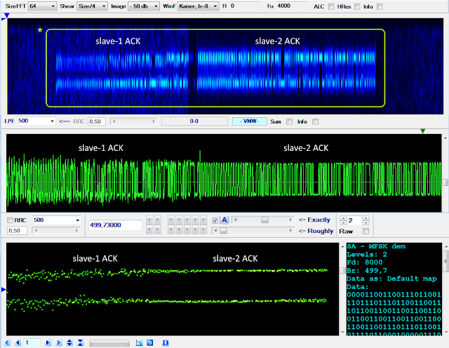
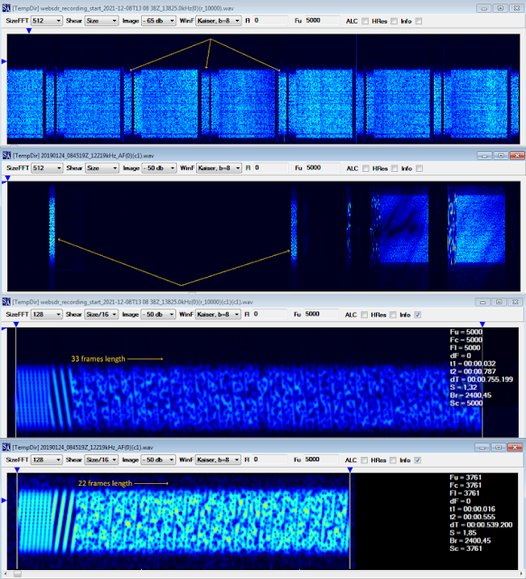
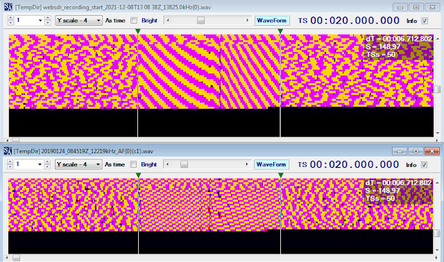
3. Transmission structure
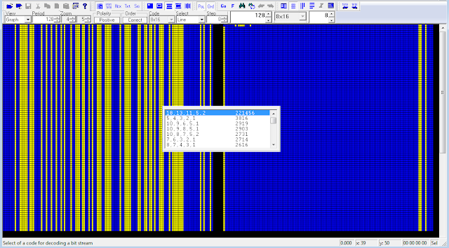
Below the start of what are considered test messages is depicted. 

3.1. Bit sync
Before message transmission starts, bit reversals (a ‘meandr’ in Russian) is transmitted to enable bit synchronization. This is followed by a separator code word (000000 or 11111) or just a number of binary ‘0s’.

3.2. ‘Sync’ group
This group never varies and contains 6 6-bit code words from the figures range arranged as 4 x 100101 + 3 x 110001 followed by a separator:

100101
100101
100101
100101

110001
110001

000000

 Polarity is shown in normal mode.

3.3. ‘Preamble’ group
The ‘preamble’ group contains 7 code words with two different, but varying values arranged as 4 x 1st code word + 3 x 2nd code word. If data following the ‘preamble’ group is encoded as 5 figure groups, the preamble is followed by a separator code word. Polarity is shown in normal mode.  Given the information in Table IV, it is clear that the group cannot be a bit counter as the preamble group covers four different message lengths.

Table IV

3.4. Message format
Data may be transmitted either as five figure-groups separated by a separator character or a stream of characters. In the first case, a separator character also separates the data group from the End-Of-Message group. If data is encoded as a stream, all 16 6-bit characters are used, except EOM, and data is not separated from the EOM group by a separator code word.

3.5. End-Of-Message group
Polarity is shown in inverted mode.

010000  0
011101  6
011101  6
010000  0
100001  EOT

3.5.1. EOT character
The EOM group ends with an EOT character, 100001.

4. Unresolved issues
- Confirmation of the proper arrangement of the d2, d1 and d0 data bits;
- Is the ‘Sync’ group in fact a synchronization group, i.e. is it the same for all messages disregarding priority, contents …? (the reason for raising this issue is the simplicity of this group – normally a synchronization group or unique word would be constructed in such a way and with such a length to obtain optimum resilience against distortions and noise);
- The function of the ‘preamble’ group.

25 November 2021

HARRIS PSK8 2400 Bd Digital Voice, an autobaud waveform?

Discussing with my fiend ANgazu about the HARRIS Digital Voice waveform (see this post), it turns out that likely that waveform is designed to provide the autobaud feature which is coded - in our opinion - in its initial header just before the normal frames' structure. As shown in figure 1, the "presumed" autobaud header consists of 8 frames each with a duration of 13.3 ms and a length of 32 bit (given the PSK2 modulation at 2400 Bd) for a total length of 256 bit. The synchronization functions would then be performed by the preamble sequences which are transmitted every 106.6 ms.  The autobaud function it may be necessary  since, according to the RF-5800 data sheet, the narrowband digital voice mode may use MELP and LPC-10 algorithms at 2400 and 600 bps.

Fig. 1 - the presumed autobaud header

Moreover, looking at the bitstream of an entire session (figure 2) it can be argued that the shorter segments are used for the management of the voice-link (ARQ mode); selcall, link setup and link closure are performed by the HARRIS specific waveform.

Fig. 2

22 November 2021

THALES Robust MFSK-8, TRC-1752 STANAG-4285 FEC, STANAG-4539


Interesting sessions recorded some days ago on 9072.0 KHz (CF) consisting of an initial THALES Robust MFSK-8 session followed by THALES TRC-1752 STANAG-4285 + STANAG-4539 encrypeted traffic, the latter used in QAM-16 6400bps mode (figure 1).The MFSK-8 waveform uses the same tone library as 188-141A/B 2G ALE but callsigns are limited to a maximum length of 2 figures only and can also be used as a robust-data mode. Aurally and visually it is easily mistaken for a normal ALE since the 250 Hz spaced eight tones and 125Bd speed. 
 
Fig. 1

Direction Finding tests, TDoA method,  point to center of France as shown below in figure 2:
 
Fig. 2 - Direction Finding tests

It must be said that the TRC-1752 modem is a bit old and therefore has probably been replaced by the new TRC-177x multi-mode modems.


19 November 2021

Harris RF-5800 Digital Voice PSK8 serial waveform (yet another 106.6 ms ACF)

A friend of mine sent me these signals consisting of a complete session utilizing the Harris 600/2400 bps Digital Voice (DV) mode:

1- selcall & link setup
2- 600/2400 bps vocoder PSK segments
3- link terminate

Fig. 1 - Harris Digital Voice mode session

Selcall is quite clear:  it's an MSK/OQPSK modulation at 2000 Baud speed, followed by short MFSK-8 125 Baud in non-standard MS-188-141A fomat, ACF is 50 ms (100 bit) and the resulting bitstream is characterized by the presence of the usual pattern (figures 2a, 2b).

Fig. 2a - Harris selcall MSK/OQPSK part

Fig. 2b - Harris selcall MFSK segment part

The VD mode PSK8 serial waveform is used only when a voice link is selected, although it also allows data to be sent over the same link; both data and voice are secured with Citadel encryption. Its ACF is the quite common 106.6 ms and that causes false-positive STANAG-4285 detections by decoders. As shown in figures 3a 3b, each frame consists of 256 tribit symbols, according to SA raster and bitstream each frame consisting of 66 sync sequence symbols (instead of 80 as in other similar 106.6 ACF waveforms), followed by a data block consisting of 190 symbols. The sync sequence is transmitted recurrently every 106.6 ms and uses PSK2 modulation.

Fig. 3a - Harris VD PSK8 serial

Fig. 3b - Harris VD framing

From Harris RF-5800 datasheet: "The digital voice mode utilizes the latest military MELP and LPC-10 algorithms for high-quality secure narrowband voice at 2400 bps. The Harris 600 bps vocoders extend the communication range beyond conventional 2400 bps systems." [1]

About the 106.6 ms ACF waveforms (figure 4), as said here, it seems that decoders such as Sorcerer and therefore also K500 try to identify a signal by measuring its ACF and comparing it against an internal table that allows the identification: likely, the length of the ACF and the initial PSK2 sync sequence mislead the decoders which consequently give a false positive STANAG-4285 id.

Fig. 4 - some common 106.6 ms ACF waveforms


https://disk.yandex.com/d/jMGcjN4lD8RH9Q 

[1] https://disk.yandex.com/i/sFOl3aX98-d6SQ


16 November 2021

CIS OFDM-121 system


Unid Russian OFDM-121 system recently heard on 11071.0 KHz (CF) until monday morning, frequency spacing between channels is 25 Hz, symbol rate in channels is 21 Baud, the used modulation seems to be a form of PSK4. As from figure 1, not all of the 121 available channels are used and it's possible to note a different arrangement of the channels in different days. The modulation used in the 2400Bd bursts preceeding the OFDM segments remains to understand, although there is a prevalence of PSK2 blocks.

Fig. 1

For what concerns the 2400Bd bursts which preceede the OFDM segments, I could not get a clean constellation; anyway looking at SA phase detector and 2nd order harmonics (figure 2), I think it is some kind of PSK4 modulation.
 
Fig. 2 - 2nd order harmonics, phase detector e constellation
 
The ACF has a 20ms value (figure 3) that makes 48 over-the-air symbols per frame, each frame apparently consisting of 32 unknown data symbols followed by 16 known symbols.
 
Fig. 3 - 2400Bd bursts framing

Apparently, this is one of the command and control systems and is associated with the recent military exercises in Belarus. Direction Finding indicate the Moscow area as Tx site location, as shown in figure 3.

Fig. 3

https://disk.yandex.com/d/qQrCn43mL0UO1Q