Just
a few unpretending notes as a result of web searches regarding the
datalink signal, we have currently been monitoring, in particular
about the format (69,48), where
48 bits are data, that for example can be heard on 6123.5 kHz, USB
during daytime. The information below refers mostly to the AI-011
(АИ-011)
device [1]: a DCE (Data Communication Equipment) for mobile systems
designed to protect and transmit telecode
data
(the generic Russian term for radar data) over standard channels of
wired, cable, radio relay, tropospheric and HF communication lines.
The data transfer rate is 600 or 1200 bits/s FSK.
Please note that translating from Russian is never easy, I relied on Yandex Translate tool and the acronyms highlighted in orange are just their English translation.
AI-011 (S23) provides operation in duplex, half-duplex and simplex modes. In duplex mode, data blocks are transmitted and received simultaneously also using ARQ. In half-duplex mode the correspondents take turns in transmitting and receiving. In simplex mode the device provides either transmission or reception of data blocks. When exchanging radar information with external subscribers, it ensures the implementation of the exchange protocols:
* AKKORD-SS-PD (АККОРД-СС-ПД) in blocks of length (165, 144) and (69, 48) bits - equipment 55Ts6; in blocks of length (165, 144), (117, 96) and (69, 48) bits - equipment R-050 ;
* IRTYSH (ИРТЫШ) in blocks of length (69, 48) bits - equipment T-235-1L.
When data transmission is carried out in blocks with a length of 69 (or 117) bits, 5 of them are service bits (m, C), 16 (I) are used for error detection and correction and the remaining 48 (96) bits (K) are used for data:
 |
Fig. 1 - 69 (117) bit format
|
If bit C = 1, the four m bits indicate the address of the correspondent in binary code: when receiving a data block, the receiving device compares the address of the data block with its own address and if they do not match, the data block is ignored. In addressed mode up to 16 subscribers may be accommodated on the same communication channel. When working without an address, i.e. when C = 0, the first and second bit m1, m2 define sub-modes: the first element indicates the DRS sub-mode (FEC mode?), the second the DRO sub-mode (ARQ mode?). The third and fourth service bits m3, m4 are used only in duplex mode: m3 is used to transmit an acknowledgement of a received data block, m4 is used to signal the channel status.
The 53-bit strings (m1,m2,m3,m4 + 48-bit data + C) are fed into the FEC encoder which performs a cyclic division by the polynomial x^16+x^12+x^5+1. The 16-bit remainders (CRC bits) are then appended to the source messages. Because the transmission is synchronous, phasing (synchronization) is carried out with the help of a special pattern which differs in structure from the structure of the payload data messages and consists of a recurring sequence of 69 bits, generated by the polynomial x^8+x^6+x^5+x^4+1. While analyzing the phasing pattern, the error protection decoder circuit will generate an error signal, since the phase combination is formed on the basis of a different polynomial.
The information is transmitted to the communication channel by three types of messages with the following priority:
1. Coordinates of the radar station and information about its operating modes.
2. The coordinates of the targets and bearings on the directors of the ASP.
3. Coordinates and signs of goals (flags related to targets?) and a sign of the ROLE removal channel (automatic or PASS).
Messages of the first priority are issued three times.
I only found the format of the of the third priority message (figure 2), and according to a web source [2] it should be the T-235-1L equipment and thus the IRTYSH (69,48) algorithm... but it could be wrong or misleading.
 |
Fig. 2 - structure of the 3rd priority message (69,48)
|
In addition to radar information, AI-011 sends information about the position of the radar station, which is derived from the navigation and orientation system or from a topographic map. At the same time, X and Y coordinate values in a rectangular coordinate system are entered with signs, and the value of the height coordinate H, and also the magnitude of the angle of direction (likely referred to the target)..
Well, honestly the information I have does not allow for further progress as:
- we do not know which equipment is used and therefore which protocol is used to transfer the data, i.e. if we have to deal with the AKKORD-SS-PD (most likely yes) or the IRTYSH protocols as both provide the same data format (69,48);
- we do not know the way the three types of messages are signaled (if any) and therefore we do not know which 48-bit structure we are analyzing, i.e. it may be that the data fields of messages we observe have a different format and consequently a different interpretation than the one shown in figure 2.
However, a couple of remarks seem to be in place:
a. The value of the 4 m bits (0101 or 1010) is the same in all messages that have been demodulated, so it's reasonable to assume that the system works w/out address: if so, the right value of bit(s) C should be "0" and the DRS sub-mode set (unless all messages are addressed to a single subscriber).
b. In this regard (the value we must attribute to the bits C) the most relevant point is this allows us to assume the correct polarity of the received bitstreams. Long periods of
absence of traffic are characterized by the sending at regular intervals (about 5.4 sec) of the sequence:
010100001001111111100001011110001101000000010001110001001011100000011
or in opposite polarity:
101011110110000000011110100001110010111111101110001110110100011111100
 |
Fig. 3 - the 69-bit phasing sequence
|
Well, that sequence is just the one used for phasing (as mentioned above) since, according to the slide #24 [2]: "The
phasing sequence is a segment of a recurring 69-bit long sequence
formed by the polynomial G(Z)=Z8 + Z6 + Z5 + Z4 + 1 The phasing sequence
starts with the codeword 01010000 and ends with the codeword 00000011". Indeed, testing for this generator polynomialwe get:
01010000 10011111111000010111100011010000000100011100010010111 00000011
 |
Fig. 4
|
Thus, as supposed, the system works in "circuit" mode (bit C = 0). The
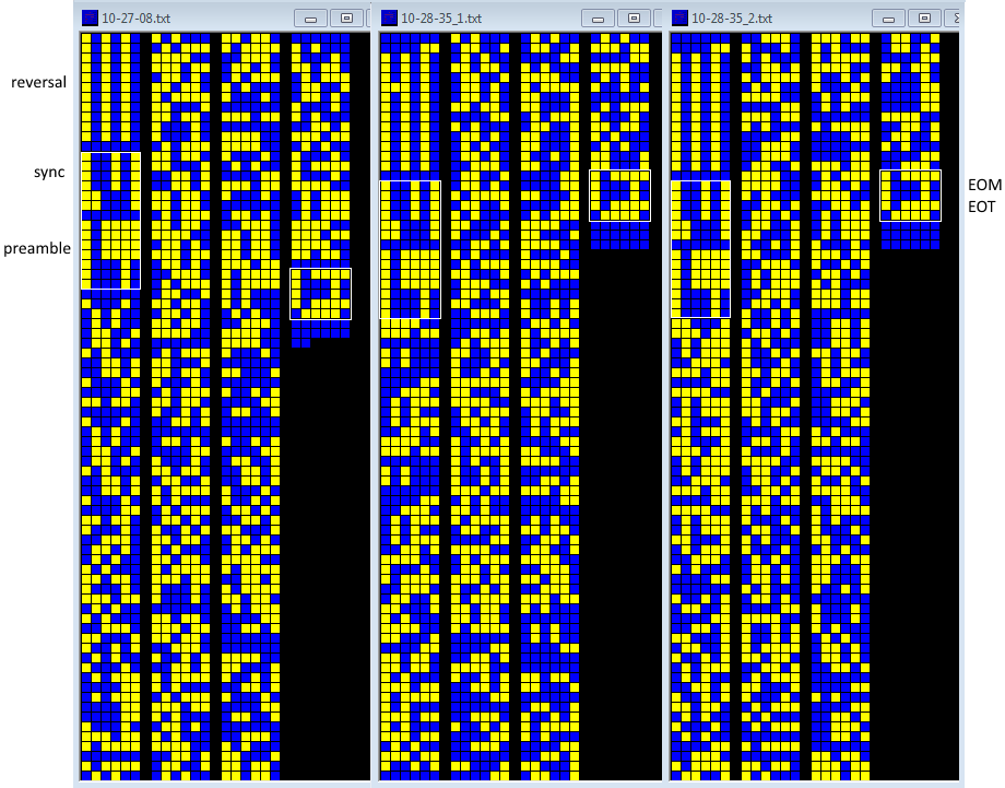
69-bit phasing sequence is also inserted within the messages streams (figures 5,6);
also note in figure 5 the sequence of "01"s that
is used to maintain the sync between messages or in absence of messages
to be sent.
 |
| Fig. 5 - 69-bit phasing sequence and "01"s before messages |
 |
Fig. 6 - 69-bit phasing in the "scrambled" (69,48) waveform
|
Checking some bistreams, it turns out that when there is no data to send (idle) the phasing sequence is sent after 94 "idle" frames, or each 95 frames considering the one containing the phasing sequence itself: by the way, some web source just refer to 95 "code sequences" [2].
 |
Fig. 7 - 69-bit phasing inserted within the idle frames
|
Obviously, the phasing sequence is also sent just after the initial reversals in the (117,96) waveform: this argues in favor of the AKKORD-SS-PD protocol since IRTYSH protocol does not provide the (117,96) format. Regarding this format, there is no precise reference to the structure of its fields in the documentation I could find in the web. From the illustrations it can be understood that the service bits are the same as those of the 96-bit format and that therefore the difference is in a double length of the data field "K".
The lack of such indications suggests that the 117-bit format sends a double number of data : the pattern sent in the second 48-bit part of the message in the bitstream of figure 8 can support this assumption. By the way, that pattern may be generated by the polynomial x^9+x^8+x+1.
 |
| Fig. 8 - 69-bit phasing in the "scrambled" (117,96) waveform |
c. Assuming that the bitstreams are structured according to figure 2 (format of the third priority message), you may notice that the first byte of the messages (fields: a, b, c, d, e) alternately always assumes the same values and that suggests that the same "type" (priority) of message is being transmitted:
m a b c d e T H X Y
1010 110 0 0 11 1 01100001 00010101 0 11001000000 1 10001111000 0
1010 000 0 1 01 0 01100001 10100000 0 00001100001 0 00100100101 0
1010 110 0 0 01 1 00000101 00010100 0 11101010100 0 10011110011 0
1010 000 0 1 01 0 00000101 00010000 0 00001100011 0 10000000110 0
1010 110 0 0 11 1 01100000 00010100 0 11101011000 0 10011110011 0
1010 000 0 1 01 0 01100000 10100000 0 00001100011 0 10000000101 0
Likewise, the values of the T (time of location) field are repeated either individually or in groups:
m a b c d e T H X Y
1010 110 0 0 11 1 01100001 00010101 0 11001000000 1 10001111000 0
1010 000 0 1 01 0 01100001 10100000 0 00001100001 0 00100100101 0
1010 110 0 0 01 1 00000101 00010100 0 11101010100 0 10011110011 0
1010 000 0 1 01 0 00000101 00010000 0 00001100011 0 10000000110 0
1010 110 0 0 11 1 01100000 00010100 0 11101011000 0 10011110011 0
1010 000 0 1 01 0 01100000 10100000 0 00001100011 0 10000000101 0
Sometimes blank messages are sent, probably to hide the radar's position or other sensitive information from "prying" eyes:
m a b c d e T H X Y
1010 000 0 1 01 0 01011100 01010000 0 00001100001 1 00100001100 0
1010 110 0 0 10 1 01010101 00100000 1 10110001111 0 10110011110 0
1010 000 0 1 01 0 01010101 01010000 0 00001100001 1 10000000010 0
1010 000 1 0 01 0 01010011 00000011 0 00000000000 0 00000000000 0
1010 000 1 0 01 0 01010100 00000011 0 00000000000 0 00000000000 0
1010 000 1 0 01 0 01010101 00000011 0 00000000000 0 00000000000 0
1010 000 1 0 01 0 01001101 00000011 0 00000000000 0 00000000000 0
1010 000 1 0 01 0 01011000 00000011 0 00000000000 0 00000000000 0
1010 000 1 0 01 0 01011010 00000011 0 00000000000 0 00000000000 0
1010 000 1 0 01 0 01011100 00000011 0 00000000000 0 00000000000 0
1010 000 1 0 01 0 00000111 00000011 0 00000000000 0 00000000000 0
1010 000 1 0 01 0 00001001 00000011 0 00000000000 0 00000000000 0
1010 000 1 0 01 0 00001100 00000011 0 00000000000 0 00000000000 0
1010 000 1 0 01 0 00010110 00000011 0 00000000000 0 00000000000 0
1010 000 1 0 01 0 00011101 00000011 0 00000000000 0 00000000000 0
1010 000 1 0 01 0 00100000 00000011 0 00000000000 0 00000000000 0
1010 110 0 0 10 1 00100010 00100000 1 10111011010 0 00111111100 0
1010 000 0 1 01 0 00100010 01010000 0 00001000010 0 11100010101 0
1010 110 0 0 10 1 00100010 00100000 1 10111011000 0 00111111010 0
1010 000 0 1 01 0 00100010 01010000 0 00001000010 0 11100010101 0
However, it should be noted
that 8 bits are definitely too few to represent a significant time marker. Maybe
the actual "time" field is formed by the join of two or more fields - or
even frames - since at least 5 HEX are required to store
the HH:MM:SS value in seconds (0x0 - 0x1517F, ie the time of day w/out
fractions of second). Furthermore,
it is not clear whether they refer to UTC time, local time. Moscow time, or some
reference (epoch) of the measurement system. Unfortunately there is no reference to this topic in the info I could find.
The possibility that a "message" is actually formed by joining two frames can be confirmed by the fact that the (69,48) frames are transmitted grouped in even numbers (excluded the interseped "phasing/sync" frames), this would also explain the use of the format (117,96). Furthermore, after removal idle frames, service bits and CRC, the data stream exhibits a strong period of 96-bit length.
 |
Fig. 9 - 96-bit period of data stream
|
It would be noted in figure 9 that most of the data is repeated in regular groups. Without information about the actual meanings and lengths of the message
fields and the used endianness, a large field of hypotheses opens up: several
solutions can be tried by processing the bitstreams with a spreadsheet
to (re)organize, filter, sort and join the data fields [3].
[1] https://vunivere.ru/work3160/page51
[2] https://disk.yandex.com/i/foPNyfiDpCHGPw
[3] https://disk.yandex.com/d/dTCHkBScBu_WMA
[4] https://studizba.com/files/show/doc/209357-4-1.html AKKORD-SS-PD (AKKORD-165)
[5] https://studbooks.net/1194685/bzhd/razrabotka_funktsionalnoy_shemy_peredayuschey_chasti