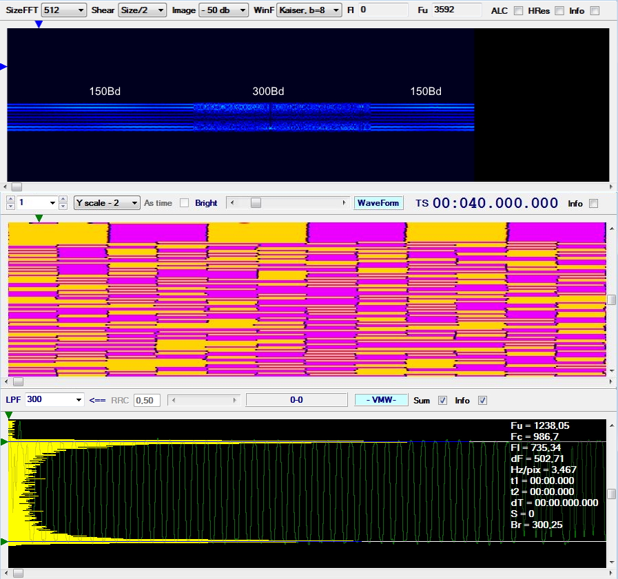
This is not the first time I have had the opportunity to study the 300Bd/500Hz FSK waveform (of Russian/CIS origin), which I have encountered in different configurations — for instance, with 255/366-bit framing, or with reversal preambles transmitted at 150 baud [1]. This time, the opportunity was provided by my friend Mario, who kindly sent me some recordings of his intercepts, captured via KiwiSDRs located in Japan (Nagano and Hokkaido). The intercepts were recorded on June 23rd, between 0848 and 0944 UTC. These are almost certainly Russian Navy voice and data transmissions, likely between the Russian Pacific Fleet HQ in Vladivostok or the Sovetskaya Gavan Naval Station (a submarine base) and a vessel. The traffic consists of voice coordination followed by tactical data bursts using FSK 300Bd/500Hz modulation on a negotiated frequency (Figure 1).
 |
| Fig. 1: Voice link setup on 8439 kHz (top) followed by FSK 300Bd/500Hz data bursts on 9100 kHz (bottom) |
The voice comm intercept occurred on 8439 kHz, which is probably a primary calling/hailing frequency. In a naval net, a major shore station or flagship (the NCS, Net Control Station) monitors this frequency continuously, acting as a guard station for the net. Subordinate mobile units check in briefly on this primary frequency just long enough to establish initial contact. Because the primary frequency must remain clear for other assets to report in, the calling unit requests a shift to a discrete tactical channel to send the follow-on data traffic.
Below, the text transcript and corresponding translation of the voice communication.
| Russian (original) | English (translation) |
|---|---|
| Волнобой, я Грейдер. Волнобой, я Грейдер. Волнобой, я Грейдер. Как слышно? Прием. | Volnoboy, this is Greyder. Volnoboy, this is Greyder. Volnoboy, this is Greyder. How do you read? Over. |
| Волнобой, я Грейдер. Волнобой, я Грейдер. Следи. Вызови меня на червячке девять-один-ноль-ноль, девять-один-ноль-ноль. Как понял? | Volnoboy, this is Greyder. Volnoboy, this is Greyder. Keep listening. QSY to vernier* nine-one-zero-zero, nine-one-zero-zero. How copy? |
| Я Грейдер. Прием. | This is Greyder. Over. |
*"Vernier" (червячок, lit. "little worm") — Russian radio slang for the fine-tuning dial, here indicating the secondary frequency.
Callsign: Volnoboy (Волнобой - "Breakwater") — Called Station, likely Net Control Station (NCS).The callsign evokes a fixed, protective structure, consistent with a shore-based command facility or a flagship unit acting as the control node.
Callsign: Greyder (Грейдер - "Grader") — Calling Station / Initiator. The callsign references mobile equipment, suggesting a an auxiliary/support vessel or a subordinate combatant establishing a tactical link.
In Soviet/Russian doctrine, callsigns are not fully arbitrary but follow category-based semantic conventions, "heavy/permanent/protective" nouns for fixed command stations or flagship units, and "mobile/task-oriented" nouns for subordinate tactical units. This reinforces the assessment of Volnoboy as NCS and Greyder as the mobile calling unit.
If my guess is correct (!), i.e. Volnoboy is the ashore NCS, there is an ideological and technological divergence between NATO and the Russian Navies:
1. The NATO Paradigm: Continuous Broadcasts (FAB). NATO utilizes the BRASS (Broadcast, Ship-Shore and Maritime Rear Link System) architecture. Shore-based Net Control Stations broadcast continuously and use FAB (Frequency Availability Broadcast) to tell the fleet exactly which frequencies are currently free for ship-shore comms. The Philosophy: Maximum protection for the ship. By listening passively to the broadcast, ships maintain total EMCON (Emission Control). The ship only transmits a brief burst to establish the link on the best available frequency. The fixed shore station takes 100% of the RF exposure.
2. The Russian Paradigm: Tactical Shadowing ("The Worm"). The intercept between Greyder and Volnoboy shows the exact opposite workflow. The Russian Navy relies heavily on "skedy" (rigidly scheduled radio appointments) and paper matrixes. Stations meet on a known primary calling frequency simply to confirm mutual contact and readability. The mobile unit (Greyder) immediately directs the shore station (Volnoboy) to transition to a secondary tactical channel ("the little worm 9100").
 |
| Fig. 2 : main FSK parameters (300 Bd/500Hz) |
 |
| Fig. 3: 80 ms period |
The demodulated bitstream shows a 24-bit period (corresponding to the 80 ms duration visible in the bitmap in Figure 3), the last of which is the phasing bit (the final column of "0s"). The data are preceded by a 240-bit sequence generated by the polynomial x^12+x^10+x^9+x^3+1.
 |
| Fig. 4: demodulated bitstream |
After removing the preamble/sync sequence and inverting the 9th column of the stream, a clear H(24,16) coding was found, ie 16-bit data followed by a 8-bit CRC. Coding is performed using the following Hamming parity check (8,24) matrix:
1 0 1 1 0 0 1 0 1 1 1 1 1 0 0 0 1 0 0 0 0 0 0 0
0 1 0 1 1 0 0 1 0 1 1 1 1 1 0 0 0 1 0 0 0 0 0 0
0 0 1 0 1 1 0 0 1 0 1 1 1 1 1 0 0 0 1 0 0 0 0 0
0 0 0 1 0 1 1 0 0 1 0 1 1 1 1 1 0 0 0 1 0 0 0 0
0 0 1 1 1 0 0 1 1 1 0 1 0 1 1 1 0 0 0 0 1 0 0 0
1 0 1 0 1 1 1 0 0 0 0 1 0 0 1 1 0 0 0 0 0 1 0 0
0 1 1 0 0 1 0 1 1 1 1 1 0 0 0 1 0 0 0 0 0 0 1 0
0 0 0 0 0 0 0 0 0 0 0 0 0 0 0 0 0 0 0 0 0 0 0 1
As demonstrated in Figure 5, the received CRC (left) matches the computed CRC (right). The latter is obtained by applying the (8,16) check sub-matrix shown above to the 16-bit data portion of the demodulated bitstream.
 |
| Fig. 5: received CRC (left) vs computed CRC (right) |
Coding verification is carried out by comparing each line of encoded data with every row of the check sub-matrix: for each row #n, the number of vertical matches between the "ones" in the encoded line and the "ones" in that row is counted. If the count is even, CRC bit #n will be "0"; if the count is odd, CRC bit #n will be "1".
Example: CRC computation for the first row of the encoded data:
DATA CRC
1 1 1 0 1 1 1 0 0 1 1 1 1 0 1 1 1 0 1 1 0 0 1 0
1 1 1 0 0 0 0 0 1 0 1 0 1 1 0 1 1 0 1 1 0 1 1 0
0 0 1 0 0 0 1 1 0 0 0 1 0 0 0 0 1 0 0 0 1 1 1 0
0 1 1 1 1 1 0 1 0 0 1 0 1 1 0 0 0 1 0 0 1 1 1 0
1 1 0 0 1 0 1 1 1 1 0 1 1 1 0 1 0 1 1 0 1 1 0 0
1 0 1 1 1 0 1 0 1 0 0 0 1 0 0 1 0 1 0 0 1 1 1 0
0 0 1 0 0 0 0 1 0 1 1 1 0 1 0 0 0 1 0 1 1 0 1 0
1 0 1 0 1 1 1 1 1 1 0 0 0 0 0 0 1 1 0 1 1 1 1 0
1 1 0 1 1 0 1 1 1 1 0 1 1 0 1 1 1 1 1 1 0 0 0 0
0 0 1 0 1 0 0 0 1 0 1 0 0 0 0 1 1 0 0 1 0 1 0 0
1 1 0 0 1 1 1 0 0 0 0 1 0 0 0 0 1 1 1 1 0 1 1 0
0 0 0 1 1 1 0 0 0 1 0 1 1 0 0 0 0 1 0 1 0 1 1 0
CHECK SUB-MATRIX
1 0 1 1 0 0 1 0 1 1 1 1 1 0 0 0
0 1 0 1 1 0 0 1 0 1 1 1 1 1 0 0
0 0 1 0 1 1 0 0 1 0 1 1 1 1 1 0
0 0 0 1 0 1 1 0 0 1 0 1 1 1 1 1
0 0 1 1 1 0 0 1 1 1 0 1 0 1 1 1
1 0 1 0 1 1 1 0 0 0 0 1 0 0 1 1
0 1 1 0 0 1 0 1 1 1 1 1 0 0 0 1
0 0 0 0 0 0 0 0 0 0 0 0 0 0 0 0
1 1 1 0 1 1 1 0 0 1 1 1 1 0 1 1
1 0 1 1 0 0 1 0 1 1 1 1 1 0 0 0 check sub-matrix row #1
7 matches (odd), CRC bit #1 value: 1
1 1 1 0 1 1 1 0 0 1 1 1 1 0 1 1
0 1 0 1 1 0 0 1 0 1 1 1 1 1 0 0 check sub-matrix row #2
6 matches (even), CRC bit #2 value: 0
1 1 1 0 1 1 1 0 0 1 1 1 1 0 1 1
0 0 1 0 1 1 0 0 1 0 1 1 1 1 1 0 check sub-matrix row #3
7 matches (odd), CRC bit #3 value: 1
1 1 1 0 1 1 1 0 0 1 1 1 1 0 1 1
0 0 0 1 0 1 1 0 0 1 0 1 1 1 1 1 check sub-matrix row #4
7 matches (odd), CRC bit #4 value: 1
1 1 1 0 1 1 1 0 0 1 1 1 1 0 1 1
0 0 1 1 1 0 0 1 1 1 0 1 0 1 1 1 check sub-matrix row #5
6 matches (even), CRC bit #5 value: 0
1 1 1 0 1 1 1 0 0 1 1 1 1 0 1 1
1 0 1 0 1 1 1 0 0 0 0 1 0 0 1 1 check sub-matrix row #6
8 matches (even), CRC bit #6 value: 0
1 1 1 0 1 1 1 0 0 1 1 1 1 0 1 1
0 1 1 0 0 1 0 1 1 1 1 1 0 0 0 1 check sub-matrix row #7
7 matches (odd), CRC bit #7 value: 1
1 1 1 0 1 1 1 0 0 1 1 1 1 0 1 1
0 0 0 0 0 0 0 0 0 0 0 0 0 0 0 0 check sub-matrix row #8
no matches (zero is even), CRC bit #8 value: 0
By the way, I used a short Octave script to compute the CRC string.
This intercept illustrates a type of Russian Fleet HF procedure: a brief voice hail on 8439 kHz to establish contact and negotiate a shift frequency, followed by short FSK 300Bd/500Hz data bursts on 9100 kHz carrying the operational traffic. The callsign roles and QSY direction are consistent with a doctrine that differs structurally from the NATO FAB/BRASS model, with the mobile unit dictating the shift and the shore station absorbing the RF exposure.
Thanks to Mario for sharing the KiwiSDR recordings that made this analysis possible.
https://disk.yandex.com/d/mgLcnpLJOLGS9Q
(1) Greyder asked the question and Volnoboy answered it. Greyder heard the response and moved to 9100 kHz to transmit its data traffic, but most likely the HF skip zone completely hid Volnoboy's voice from the KiwiSDR in Japan. The Japanese receiver was likely sitting in a dead zone where Volnoboy's signal skipped over the antenna, while Greyder's signal — transmitted from a different position — had a more favorable propagation path.
[2] http://i56578-swl.blogspot.com/search/label/FSK%20300Bd%2F500