Showing posts with label Akula. Show all posts

24 April 2025

CIS-Navy & Akula transmission

My friend Mario often monitors the frequency of 9201.0 KHz/USB in search of "Akula" signals: he mainly uses a KiwiSDR receiver located in Japan (Azumino-city, Nagano) [1] and it seems that this frequency (certainly one of the many) is quite active for this kind of transmissions, as collected by my friend Dave too. Most of the time it is usually a pair of signals that repeat at irregular intervals.
A few days ago he kindly sent me an interesting and "curious" recording of a transmission in which both an FSK 50Bd/1000 signal and Akula (FSK 500Bd/1000) are used with a central frequency of 9202 KHz (Figs. 1,2) 

Fig. 1

Fig. 2

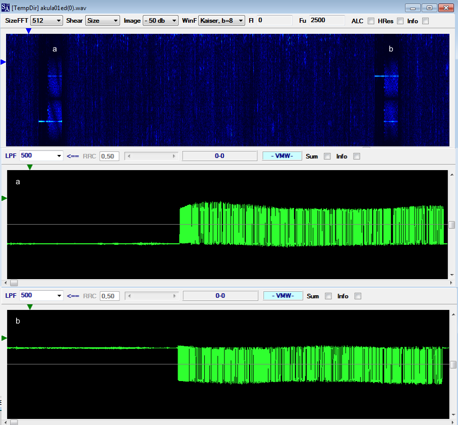
The first thing that catches the eye is the particular "shape" of the Akula signals in which the well-known initial synchronization and preamble groups are missing but the EOM + EOT groups (101111 100010 100010 101111 011110) are exactly in their place, as can be seen from the demodulated bitstream in Figure 3. Just one year ago I had already come across these (let's call them) "anomalies" [2]. "It could depend on a malfunction of the modem or on the receiver's attack time" my friend cryptomaster says.

Fig. 3 - Akula bitstream
 
The most interesting thing however is the presence of a 50Bd/1000 FSK modulation preceding an Akula burst: something I had never seen before (and not even that type of FSK modulation). After demodulating it and reshaped to a 7-bit format, in addition to the initial inversions, I noticed a final sequence composed of five identical 7-bit words "000100" which - as far as I know - is the typical EOM sequence used in the CIS-Navy waveform (also known by the nicknames T-600, BEE-36, CIS 36-50). However, compared to the latter, it lacks the initial part consisting of a sequence of 2 bit sequence 
(usually) "100001010010111110000101001101011010110101101"
followed by 70-bit Initialization Vector (ten 7-bit words) that is repeated twice (Figure 4).

Fig. 4 - FSK 50Bd/1000 bitstream

As per previous analysis of the CIS-Navy waveform [3], its payload data consists of 5-bit characters coded into 7-bit sequence with a fixed ratio of '1's vs. '0's of 4 to 3 (or vice versa, depending on polarity of reception) so I decided to check the 4:3 ratio in this demodulated bitstream: the result (97.5%) indicates a very good probability of success.
 
Fig. 5 - 4:3 ratio in FSK 50Bd/1000 bitstream

CIS-Navy waveform has been logged with different Baud rates (36, 50, 75, 100 and 150) and shifts (85, 125, 250 and 500 Hz) so, likely, that's another variation.

https://disk.yandex.com/d/E29PupqpJg3UTQ

[1] http://jf0fumkiwi.ddns.net:8073/?f=9201.00usbz9
[2] http://i56578-swl.blogspot.com/2024/05/akula-always-reserves-surprises.html
[3] http://i56578-swl.blogspot.com/2016/10/cis-navy-50bd200-fsk-t600-bee-36-cis-36.html

4 June 2024

does wideband Akula use a FBMC-SS waveform?

The idea for this post came to me while talking with my friend ANgazu (from radiofrecuencias.es) about an emerging Spread Spectrum (SS) technique that uses MultiCarrier waveforms (MC-SS). The question that came up was whether the so-called "wideband" Akula (15 × 500Bd DBPSK) used this type of spread spectrum technique, specifically a Filter Bank based multicarrier waveform (FBMC-SS).

I demodulated the 15 channels and found that they carry the same information carried by the following "usual" FSK 500Bd/1000 transmission (Figs. 1,2,3).

Fig. 1 - channels 1-6

Fig. 2 - channels 7-12
Fig. 3 - channels 13-15 and FSK segment

Channel separation is 2 Khz, quite enough to allow a easy detection and filtering of the subcarriers, for a total bandwidth of 30 KHz (Figure 4).  As one can see, wideband Akula's spectrum is very different from other  multicarrier waveforms like OFDM or mPSK (if only for the used bandwidth).

Fig. 4 - wideband Akula and its spettral occupancy

Two popular spread spectrum systems in usage today are frequency-hopping spread spectrum (FH-SS) and direct-sequence spread spectrum (DS-SS). The basic idea of the multicarrier spread spectrum (MC-SS) is to transmit redundant information on multiple subcarriers with a slight phase variation on each one. The Filter Bank MultiCarrier Spread Spectrum (FBMC-SS) waveform, as its name implies, makes use of a filter bank to develop a spread spectrum technique. With this waveform, data symbols  are spread across a number of non-overlapping adjacent subcarriers unlike in DS-SS, where spreading is performed across time, as it happens using Walsh Direct Sequence Spread Spectrum (Walsh DS-SS). The carriers are positioned in a way that the receiver can isolate a single channel by means of selective filtering without interchannel interference. One unique feature of this FBMC-SS construction is that it can easily mask portions of the band that are corrupted by interference or jamming intended by a foe: indeed, a narrow band interference stays well isolated and does not affect more than a few subcarriers (it is no coincidence that I heard wideband Akula using a remote SpyServer receiver located in Ukraine).
 
I don't have the tools to say for sure that they use a FBMC-SS waveform, but there are some elements that lead to this conclusion. In the links below you can download, in addition to the signal and the channel demodulations, interesting documentation about FBMC-SS so that people more skilled than me can comment or deny our hypothesis.


4 May 2024

Akula always reserves surprises...

A few days ago a friend of mine sent me some recordings of a serie of FSK bursts which had the same keying speed and shift (500Bd/1000Hz) as the "Akula" waveform but which differed due to the lack of the sync and preamble sequences as well as the IVs, as shown in Figure 1.

Fig. 1

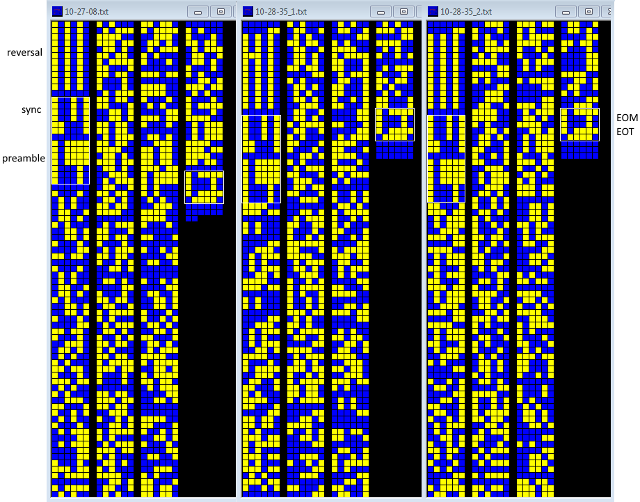
The demodulation of these bursts, however, reserved a surprise: although the sync and preamble groups were missing, the EOM + EOT groups (101111 100010 100010 101111 011110) were exactly the same as Akula (see Figure 2).

Fig. 2 - some of the demodulated bitstreams

There and then I gave up and thought of a common EOM + EOT sequences perhaps also used in other CIS waveforms, until this morning I accidentally came across an Akula traffic on 8284.0 KHz (cf)... and I found a burst with the same characteristics, i.e. without the usual sync-preamble-IVs groups, among other "complete" bursts (1): say a kind of  Akula "data-only" burst (Figure 3). I had ever seen it before. 


Fig. 3 - a so-called Akula "data-only" burst
 

Could it be the same "physical" (possibly faulty) modem? Difficult to say. My friend's recordings date back to April 30th (three days ago) and made using a remote KiwiSDR in Azumino-city, Nagano Japan and therefore probably a vessel on-going in the Pacific Ocean; my recordings were made using an AirSpy server located in Tofta, Goland Is. Sweden and with an excellent SNR value: a clue of a vessel on-going in nearby waters. And yes, one could object that the propagation takes strange paths, and that's ok, but assuming the same area of origin of the signal (and thus the same vessel/modem), my listening would be quite unlikely given the time and the used frequency (Figure 4).

Fig. 4 - VOACAP chart

 
Among other things, the durations of the Akula transmissions recorded in Japan are unusual compared to those we are used to seeing, i.e. just short transmissions consisting of a few bursts likely to avoid triangulation by the "foe".

The question remains: faulty modems? a mode of Akula messaging that I don't know or have never met? or just mere coincidences or wrong receiver settings (ie AGC)?
Further successful registrations will (hopefully) help...

 
(1) As said, the other bursts of my recorded transmission have the Akula well-known format (1), ie:
- sync group (6 code words: 4x100101 + 2x110001) followed by 6-bit "0"s separator
- preamble group (7 code words arranged as: 4x1st code word + 3x2nd code word)
- data
- End-Of-Message group + EOT group (five code words: 101111 100010 100010 101111 011110) 


9 November 2023

Akula 250Bd/500 FSK version

A friend of mine, whom I'm grateful, sent me this interesting and quite rare example of the Akula 250Bd/500 FSK waveform. Transmission was recorded on 9202 KHz around 0800 UTC using a Japanese SDR: as you see, the values of the FSK parameters are the half of the usual ones (500Bd/1000) 

Fig. 1 - Akula 250Bd/500

The demodulated bitstream shows the normal Akula "stuff" (Figure 2):
- reversals
- sync group (6 code words followed by 6-bit "0"s separator)
- preamble group (7 code words with two different, but varying values arranged as 4 x 1st code word + 3 x 2nd code word)
- data block
- End-Of-Message group + EOT group (which never varies and consists of the five code words 101111 100010 100010 101111 011110)

Also notice in Figure 2 the slight difference between the preamble of this sample:
3 x 100101 + 110101 + 2 x 110001
and the characteristic one obtained from the demodulation of the 500Bd/1000 waveform:
4 x 100101 + 2 x 110001
further registrations are needed before we can say that this is the characteristic preamble of the 250Bd/500 waveform.

Fig. 2 - Akula 250Bd/500 demodulated bitstream

It's worth noting in Figure 1,3 the continuous carrier in absence of messages, as already seen in other recordings [1]: probably this is due to the adopted ship-shore "paradigma". While in many of the western navies the shore stations are used to broadcast a list of available listening frequency (FABs/CARBs) (1), it could be that the Russian shore stations transmit a carrier on their known listening frequencies at scheduled times on behalf of subs which have something to comunicate to the shore station itself.  That's obviously my and my frield's guess.

Fig. 3

It's very interesting to note that a day after, and on the same frequency, a short speech was noted: "GREYDER ya DALNIE", more over the Ministry of Defense of the Russian Federation web site reports about an anti-submarine exercise in Peter the Great Bay by the Pacific Fleet just on 8th November (Figure 4) [3]. Note that "Peter the Great Bay" is located in the Sea of Japan, northwestern Pacific Ocean, in the Maritime (Primorye) region of far eastern Russia and that the Akula sample was heard using a remote KiwiSDR in Nagano, Japan. Just a coincidence?

Fig. 4 - https://function.mil.ru/news_page/country/more.htm?id=12484855@egNews

https://disk.yandex.com/d/kGyl5tQco6hKWg

(1) CARB is the acronym for Channel Availability and Receipt Broadcast, these transmissions radiate information on the frequencies available for ship-shore traffic and to pass control and receipt messages; sometimes also indicated as FAB or Frequency Availability Broadcast. These procedures are used to automatically perform a channel-link before a message could be sent [2]. 

[1] http://i56578-swl.blogspot.com/2022/04/akula-quite-unusual-session.html
[2] http://i56578-swl.blogspot.com/search/label/FAB
[3] https://function.mil.ru/news_page/country/more.htm?id=12484855@egNews

14 June 2023

wideband Akula

A dear friend of mine sent me a very very interesting recording of a short Akula transmission consisting of the usual Akula 500Bd/1000 FSK preceeded by 15 DBPSK modulated tones, symbol rate of 500Bd (as Akula II).

Fig. 1

As already discussed in a previous post [1] the 15 DBPSK channels and the FSK segment transport the same data (Figure 2), probably using such a width signal - about 30 kHz - should provide good noise immunity. 

Figure 2

Most interestingly, the signal was recorded using an SDR receiver near Kiev, so given that:
1) Akula waveforms are used for subcomms
2) signal strength is impressive (Figure 3)
the presence of Russian subs in the Black Sea could be assumed...

Figure 3 - waterfall image, thanks to my friend who recorded the signal

https://disk.yandex.com/d/HrJYX195Q9kRDw

[1] https://i56578-swl.blogspot.com/2021/02/15-channel-30khz-cis-akula-shark.html

20 June 2022

"Akula" almost always holds surprises

"Akula" almost always holds surprises when it happens to came across its transmissions, is the case of a recording kindly sent me by my friend ANgazu that is characterized by at least three points:

1) the transmitter was used as soon as it was powered-on or in-standby: you may notice a slight frequency increase of a few seconds, about 37, before reaching the working frequency (figure 1): say that it's a kind of "cold-start" maybe due to an urgency call?

Fig. 1

2) one of the bursts is sent in inverse polarity (figures 2,3)

Fig. 2

Fig. 3

3) the initial bursts consist of a train of pulses (not always of the same number) instead of the usual 500Bd BPSK (figure 4)

Fig. 4

Also notice the transmission of the lower tone before and after the messages, it seems that the involved modems have different behavior. The number of the exchanges is also unusual.

However, it must be borne in mind that the current times are ...quite "particular".

https://disk.yandex.com/d/vlIS_YkqZr3chQ 


15 April 2022

Akula: a quite unusual session

Quite unusual session of Rus-Ny "Akula" 500Bd/1000 FSK characterized by the continuous transmission of only the lowest tone before and after the messages (see figure 1), just like some Rus-Ny 50Bd/200 or even FAB broadcasts from PBB Dutch-Ny.

Fig. 1

 Notice in figure 2 the usual structure of the Akula messages:
- reversals
- "sync" group (which never varies and contains 6 code words arranged as 4 x 100101 + 3 x 110001 followed by a separator)
- "preamble" group (7 code words with two different, but varying values arranged as 4 x 1st code word + 3 x 2nd code word)
- data block
- End-Of-Message group + EOT group (which never varies and consists of the five code words 101111 100010 100010 101111 011110)

Fig. 2 - structure of Akula messages

https://disk.yandex.com/d/tqDzwGYNKw1YVQ


3 December 2021

Notes about Akula (v. 291121b)

My friend Nicola, with whom we often collaborate and whom I thank here, has been studying Akula's code for several months now and recently sent me a paper related to his work: I am very happy to publish the (current) results of his analysis, soliciting readers to express their views and comments. 

1. Introduction
Akula (the formal designation is not known) is a communication system used by the Russian navy. Originally Akula was designed as a high speed morse based communication system for submarines to avoid HF direction finding. Various sources set the maximum on-air time for these transmissions to 0.72 seconds. It was not until the USA started deploying the gigantic Wullenweber direction finding antennas that it became possible to triangulate (or multi-angulate) these transmissions.
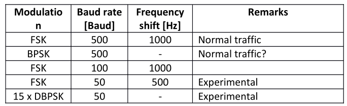
Today’s Akula normally uses FSK at 500 Baud and a 6-bit alphabet for surface communication links. A
variant called Akula II is a DBPSK burst modem for the use among other in submarine communications.
Other variants have been observed, see Table I below.

Table I

Messages intercepted have mostly consisted of encrypted streams, however messages consisting of five
figure groups have also been observed.

2. Alphabet
2.1. Preliminary approaches

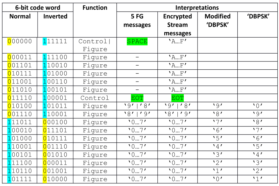
Akula utilizes a 6-bit alphabet. Until now 17 different code words have been identified. What the characters represent seems to depend on the message payload format, i.e. five-figure groups or encrypted stream. Ten characters represent the figures from 1 to 9, 6 represent the hex numbers A to F,one represents both a decimal number and SPACE and one is a control character, EOT. 

The only code words determined with certainty when these notes were begun, were ’Separator’ (000000 or 11111) and ‘EOT’ (011110 or 011110) marked in green. The codewords representing a decimal figure (0-9) have been determined from a message containing only five figure-groups, but the actual value assigned to a character was not known. However, another interpretation has been done, based on a message perceived as a test transmission in DBPSK modulation.

Table II below shows the 6-bit alphabet in use for Akula consolidating the information available at the time these notes were begun. Characters with the MSB bit set to ‘1’ in normal condition or ‘0’ in inverted condition are part of the number range 0-7, whereas the ones with the MSB bit set to ‘0’ in normal condition or ‘1’ in inverted condition are either within the range 8 – F or is a control character.

Table II - Akula 6-bit alphabet
 

Figure 1 (below, to the left) shows an interpretation, based on the assumption that the message represents the sequence “1 2 3 4 5 6 7 8 9 0” and that the group ‘4443’ in fact represents an error. However, the weak point of this interpretation is the composition of the number sequence. If one let this sequence start at ‘0’ instead of ‘1’ it will be seen that now ‘8’ and ‘9’ both start with a ‘0’ as MSB, which agrees with the previous analysis.


Fig. 1

2.2. Final approach
After investigating the messages available, a new approach was initiated based on the following analysis (1): In a message consisting of five figure groups, 10 different characters in addition to the control characters SPACE and EOT were observed, 8 with an initial ‘0’and 2 with an initial ‘1’, which must represent the numbers ‘0…9’. Analyzing a number of messages with a payload consisting of an encrypted stream identified another 6 characters with an initial ‘1’, which must represent the hexadecimal numbers ‘A…F’.

Going back to the characters identified in the five figure groups, and using the knowledge gained above, the two code words having an initial ‘1’must represent ‘8’ and ‘9’. As SPACE is used as separator between succeeding groups it cannot represent ‘0’. However, this value is mandatory in five figure-groups as well as in encrypted stream messages, thus another code word must represent the value of ‘0’, and logically it should be placed in the range of code words starting with ‘0’, which would correspond to the lower range of hexadecimal figures ordered in descending order.

This could point to an alphabet based on four binary digits plus two check bits. Comparing it to knownmethods of redundancy, a Hamming code can immediately be ruled out as it would require three check bits to protect four data bits. On the other hand, old Soviet radioteletype codes very often used just two check bits to cover 12 data bits.

Now, using the inverted mode of the code words as shown below, and testing various positions of the data bits as exponents of 2 and keeping this together with the position of the parity bits it seemed that one viable guess for the format of an Akula code word could be this:

where d3 = 2^3, d2 = 2^2, d1 = 2^1, d0 = 2^0, p1 = (d3 + d2 + d0) and p0 = (d3 + d2 + d1).

This arrangement is the logical arrangement of hexadecimal figures with the MSB leftmost. Other configurations are entirely possible as long as the MSB is kept as representing 2 3 and the positions of the check bits are fixed. Using this, Table II has been rearranged as shown below:

Table III - Rearranged Akula alphabet table with parity calculation

In Table III p0 is marked in turquoise and p1 in yellow. Parity violations are marked in red. The parity inversion for ’0’ may be explained as to avoid a continuous string of binary zero making the extraction of clocking more difficult. The same may make sense for ‘1’ and ‘4’. In the case of EOT the reason could be to establish a unique code word.

Something special surfaced when taking a closer look at a five figure-group message. No code word representing ‘9’ using the power of two calculation given above yielded a ‘9’, which should have been ‘101000’, but a hex ‘B’ ‘101011’ is used for a ‘9’. However, in encrypted stream messages a proper ‘9’ is used.

3. Transmission structure
Below the start of what are considered test messages is depicted. 

3.1. Bit sync
Before message transmission starts, bit reversals (a ‘meandr’ in Russian) is transmitted to enable bit synchronization. This is followed by a separator code word (000000 or 11111) or just a number of binary ‘0s’.

3.2. ‘Sync’ group
This group never varies and contains 6 6-bit code words from the figures range arranged as 4 x 100101 + 3 x 110001 followed by a separator:

100101
100101
100101
100101

110001
110001

000000

 Polarity is shown in normal mode.

3.3. ‘Preamble’ group
The ‘preamble’ group contains 7 code words with two different, but varying values arranged as 4 x 1st code word + 3 x 2nd code word. If data following the ‘preamble’ group is encoded as 5 figure groups, the preamble is followed by a separator code word. Polarity is shown in normal mode.  Given the information in Table IV, it is clear that the group cannot be a bit counter as the preamble group covers four different message lengths.

Table IV

3.4. Message format
Data may be transmitted either as five figure-groups separated by a separator character or a stream of characters. In the first case, a separator character also separates the data group from the End-Of-Message group. If data is encoded as a stream, all 16 6-bit characters are used, except EOM, and data is not separated from the EOM group by a separator code word.

3.5. End-Of-Message group
Polarity is shown in inverted mode.

010000  0
011101  6
011101  6
010000  0
100001  EOT

3.5.1. EOT character
The EOM group ends with an EOT character, 100001.

4. Unresolved issues
- Confirmation of the proper arrangement of the d2, d1 and d0 data bits;
- Is the ‘Sync’ group in fact a synchronization group, i.e. is it the same for all messages disregarding priority, contents …? (the reason for raising this issue is the simplicity of this group – normally a synchronization group or unique word would be constructed in such a way and with such a length to obtain optimum resilience against distortions and noise);
- The function of the ‘preamble’ group.

27 February 2021

15-channel BPSK 500Bd 30KHz, CIS (wideband?) Akula

Quite rare Akula ("Shark") [1] signal catched by my friend KarapuZ. The usual Akula 500Bd/1000 FSK2 waveform is preceeded by the transmission of 15 PSK tones (MPSK-15) lasting the same time of the FSK signal. The 15 channels are about 2200 Hz spaced and occupy a bandwidth of 30 KHz, each channel consisting of a BPSK modulated tone at the symbol rate of 500Bd (Akula II), ie the same of the following FSK2 burst; the 15 subcarriers are not orthogonal (Figs 1,2).

Fig. 1

Fig. 2
 
Either the BPSK channels and the FSK2 transport the same data and use the well-known distinctive sign "1771/"  as shown in Figure 3.
As per [1], FSK2 Akula may be descrambled using the LFSRs described by the polinomyals x^5+x^3+x+1 or x^4+x^3+1 after differential decoding: well, in this case none of the two modes (BPSK and FSK2) is successfully descrambled using the above polynomials.
 
Fig. 3 - ending parts of the demodulated bitstreams

The FSK2 signal is exactly centered on the passband of the preceeding 8th DBPSK tone (likely the "call" frequency): it could be that the FSK2 signal is targeted to "legacy" receivers while the wideband part to "stared" SDR receivers (as said, the contents are the same)... but that's only a my guess, who knows? anyway, using such a width signal (about 30 kHz) should provide good noise immunity. It's to notice how the power of the FSK signal appears spreaded on the DBPSK signals (same transmitter). 
 
The use of BPSK modulation (Akula II) is not new, as a 2015 recording demonstrates (Figure 4). Also in this sample, the FSK signal is centered on the passband of the preceeding BPSK subcarrier, although the switch time  BPSK -> FSK2 is longer than the one 15xBPSK -> FSK2. The two demodulated bitstreams - at least in this sample - are not the same (Figure 5).
 
Fig. 4 

 
Fig. 5


29 March 2018

FSK 500Bd/1000, CIS Navy Akula ("shark")


CIS Akula ("Shark") is a FSK 500Bd/1000 burst waveform used by Russian/CIS Navy in  ship-shore links, most likely by submarines. Akula is one of the most interesting signals you may meet in air: fast, unpredictable and unfrequent; see below for a little story of this signal.
Back to the signal, the waveform consists of FSK bursts modulated at speed of 500Bd and 1000Hz shift (Figure 1). A distinctive sign are the last bits of the demodulated bitstream: a sort of EOM mark "1771/" (Figure 2).

Fig. 1
Fig. 2
I worked several good quality recordings and found that they can be successfully descrambled using the LFSR described by the polinomyal x^5+x^3+x+1, after the removal of the scrambler the resulting bitstream exhibits an interesting 6-bit period (Figure 3).

Fig. 3
The same 6-bit period (Figure 4) can be obtained by descrambling the bitstream after differential decoding: in this case the scramble polynomial is x^4+x^3+1 (thanks to KarapuZ).

Fig. 4

Legacy Akula (Shark), or the so-called 49th channel, was originally a ship-shore superfast telegraph system used to transmit reports from submarines, the received transmissions were immediately relayed to HQ Navy on all available communication channels.
Transmissions did consist of ten groups of 5 digits and 0.72 secs in air. The main equipment of Akula is the sensor P-758 and the receiver P-759 (Figs 5,6), with their ancillaries, and appeared in the fleet in the late 50's. In total, more than 4,500 sets were produced. [1]

Fig. 5 - P-758
Fig. 6 - P-759
"In parallel with the development of land-based communication systems of the Navy the technical means with high-speed, security and automation were designed for surface ships and submarines. The experts of the Naval Research Institute of Communication designed special HF very-high-speed (VHS) secured communication link later named Akula (Shark). Then existing systems could not detect and not even saying of taking a bearing of VHS transmissions. In addition thanks to the usage of increased capacity (up to 15 kW) radio transmitting equipment at submarines and a set of geographically distributed land-based receiving radio centers the high-fidelity reception was possible even at range of 8-10 thousand kilometers. Navy commissioning of VHS communication means marked the new qualitative stage in the development of naval communication systems."
http://rusnavy.com/science/electronics/rv6.htm

There is an interesting story about the so-called "Project Boresight" and “lost” Soviet submarines that confirms the Akula's undetectable feature (thanks to Dave for the link):
http://jproc.ca/rrp/rrp2/boresight.html
Akula, with minor variations ("Dolphin", to be precise), is still used for long-range operational and near operational-tactical communications of the Russian Navy, perhaps the P-758IS equipment is used (Figure 7).


Fig. 7 - P-758IS

Akula messages received by shore stations are instantly relayed to the CIC of the RN on all available communication channels. Akula has also been noted in use by surface "recon" ie surveillance units and might be a method used for transmitting emergency traffic of flash precedence by Akula equipped RN units. Akula messages are copied via 135 radio reception centers of the Russian navy, keeping in mind submarine-related comms have highest priority in Russian Navy.
 
Sometimes a short BPSK 500Bd burst (Akula II) is seen before FSK Akula traffic commences, probably an  indication of capability (Figure 8).
 
Fig. 8 - Akula II burst


31 August 2020 update
Interesting 100Bd/1000 variant catched by my friend KarapuZ on 28 August:


Some logged frequencies (all CF) collected by my friend Dave:

3399 4414 4882 5338 5555 5784 6772 6836 6852 6864 6908 6920 7316 7620
7690 7734 7674 7748 8300 8500 9155 9202 9264 9372 9955 9628 10116 10192
10208 10314 10478 10659 10664 10816 10860 10888 10928 11024 11155 12312
12368 12693 13146 14266 13404 13406 14206 14208 14266 14840 14860 16104
16248 16264

[1]
http://cruiser.patosin.ru/forum/viewtopic.php?f=19&t=804&start=140
http://www.bigler.ru/forum_vb/showthread.php?t=32785
http://forum.pogranichnik.ru/.../page-33
https://vmf.informost.ru/2009/firms/crt.html