27 May 2016
21 May 2016
Unid FSK 300Bd/850
tags:
FSK 300Bd/850

This FSK signal has been heard on 6699.0 KHz (cf), manipulation speed is 300 symbols/sec (quite unusual) and the shift between tones is ~850 Hz (pics. 1,2)
 |
| pic. 1 |
 |
| pic. 2 |
The signal is continuous and exhibits a characteristic "batman-like" spectrum (pic. 3)
 |
| pic. 3 |
16 May 2016
phase keyed signals, SA, and possible wrong demodulations
tags:
Comments,
SA,
Stanag-4285
Playing with a STANAG-4285 signal and SA (Signals Analayzer) I met some problems in understanding correctly the synchronization sequence pattern of this waveform: the solution is very simple indeed and must be sought in the way the SA phase-plane module demodulator works. Below the story.
 |
| SA phase-plane demodulating a STANAG-4285 signal |
"The synchronization phase of the STANAG-4285 waveform consists of 80 symbols and is transmitted recurrently every 106.6 ms. This sequence uses 2-bit phase shift keying (2-PSK) modulation and the modulation rate is equal to 2400 bauds. The sequence is identical to a pseudorandom sequence of length 31, which is repeated periodically within the 80-symbol window, i.e., the synchronization sequence consists of 2 periods of length 31 plus the first 18 symbols of another period. A generator for the synchronization sequence is described in pic. 1. The generator polynomial is: x^5 + x^2 +1.
At the beginning of every frame the generator is initially set to the following value: 11010. The first symbol of the synchronization sequence is identical to the least significant bit of this initial value. The remaining 79 symbols are obtained by applying the clock 79 times.
The scrambling operation is carried out on reference and data symbols only, not on the synchronization sequence."
The scrambling operation is carried out on reference and data symbols only, not on the synchronization sequence."
 |
| Fig. 1 - S-4285 sync sequence generator |
Coding PSK-2 into 8-ary on air is achieved by mapping one-bit to one-symbol according to the following rule in Fig. 2:
"000" tribit symbol for bit "0" (symbol 0)
"100" tribit symbol for bit "1" (symbol 4)
The S-4285 sync sequence generator can be synthesised running a simple Lua program: since the sync sequence is not subjected to the scrambling, the output file generated by the program is just the STANAG-4285 sync sequence that I need. The synthesised pattern of the sync sequence is visible using a bitstream analyzer (Fig. 3).
"000" tribit symbol for bit "0" (symbol 0)
"100" tribit symbol for bit "1" (symbol 4)
 |
| Fig. 2 - 0-4 mapping |
 |
| Fig. 3 - synthetized sync sequence pattern using the 0-4 mapping |
Looking at a on-air STANAG-4285 demodulated by SA phase-plane, the 80 symbols sync sequence exhibits a different pattern than the one synthesised (Fig. 4)
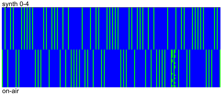 |
| Fig. 4 - synthesised 0-4 Vs on-air sync sequence patterns |
The differences with the on-air signal are more evident looking at the sync sequence generated by a STANG-4285 modem (Fig. 5)
 |
| Fig. 5 - modem Vs on-air sync sequence patterns |
while the synthesised and modem sync sequence patterns are the same, unless the polarity (Fig. 6)
Indeed, editing the mapBit() function of the Lua code adding a negative π/4 phase rotation, ie a 7-3 mapping, we get the same sync sequence pattern produced by the modem (Figs. 7,8)
 |
| Fig. 6 - synthesised 0-4 Vs modem sync sequence patterns |
Indeed, editing the mapBit() function of the Lua code adding a negative π/4 phase rotation, ie a 7-3 mapping, we get the same sync sequence pattern produced by the modem (Figs. 7,8)
local function mapBit(Ubit)
if (Ubit == "0") then
8ary_symbol = {"1","1","1"} -- # symbol number 7
else
8ary_symbol = {"0","1","1"} -- # symbol number 3
end
return 8ary_symbol
end
end
 |
| Fig. 7 - 7-3 mapping |
 |
| Fig. 8 - syntesised 7-3 Vs modem sync sequences pattern |
Editing the sync sequence generator, I found that a sequence that macthes the one of the on-air signal can be obtained by using the 4-0 mapping, ie by adding a π phase rotation as shown in Figures 9,10 (unless some uncertainties in the on-air signal):
local function mapBit(Ubit)
if (Ubit == "0") then
8ary_symbol = {"1","0","0"} -- # symbol number 4
else
8ary_symbol = {"0","0","0"} -- # symbol number 0
end
return 8ary_symbol
end
end
 |
| Fig. 9 - 4-0 mapping |
 |
| Fig. 10 - synthesised 4-0 Vs on-air sync sequence patterns |
I think that the differences between the sync sequences produced by the sythetiser and the modem and the sync sequence of the on-air signal are due to the phase-plane module of SA. SA is a signal analyzer and not a decoder, therefore its
phase-plane demodulator does not sync any particular protocol, as
it happens for example in STANAG-4285 "suited" decoders. Working with phase keyed signals, the SA phane-plane demodulator produces right interpretations and views (number of phases, angles, modulation speed, carrier frequency,...) but it may return wrong demodulated streams due to the possible phase-offset errors.
13 May 2016
Link-11 SLEW: scrambler length and ACF value
tags:
LINK-11 SLEW,
STANAG-5511
TADIL-A/Link 11 is a secure half-duplex TADIL radio link used by US and NATO that receives or transmits --but not both simultaneously-- a sequential data exchange digital link. It exchanges digital information among airborne, land-based, and ship-board tactical data systems. It is the primary means to exchange data such as radar tracking information beyond line of sight.
LINK-11 comes in two waveroms: the original Conventional Link Eleven Waveform (CLEW) and Single (serial) tone Link Eleven Waveform (SLEW).
LINK-11 comes in two waveroms: the original Conventional Link Eleven Waveform (CLEW) and Single (serial) tone Link Eleven Waveform (SLEW).

Single tone Link Eleven Waveform (SLEW) is one of the modes defined within the Link 11 NATO standard
 |
| pic. 1 |
The SLEW waveform transmission format consists of an acquisition preamble followed by two or more fields. Each 45 symbols field is followed by a 19 symbols reinsertion probe. The first field after the preamble is the header field and contains information that is used by the Combat Data System (CDS) and the encryption device. If there are data to transmit, successive data fields follow the reinsertion probe of the preceding fields (pic. 2,3).
 |
| pic. 2 SLEW waveform structure |
 |
| pic. 3 |
Running the Cross Correlation or Auto Correlaton functions, a 64 symbols or 192 bits frame are expected, but in contrast the CCF output exhibits clear and strong 320 symbols spikes corresponding to a period of 960 bits. Note that five data and reinsertion-probe pairs are arranged inside the period window (pic. 4).
 |
| pic. 4 - SLEW waveform CCF result (133.33ms) |
So, why the 133.33ms, or 320 symbols, period?
As in pic. 5, the 45 phase encoded pairs (values 0, 1, 2, 3) are mapped into tri-bit numbers (by multiplying by 2). The tri-bit numbers (0, 2, 4, 6) are used for symbol generation and scrambled to take on all 8 phase states. During the reinsertion probe, 19 tri-bits (set all to "000") are used for known symbol formation and scrambled.
 | |
| pic. 5 - SLEW wavefrom formation (reinsertion probe and data field) |
"The tri-bit numbers supplied for the symbols (both data and probe) are modulo-8 added to a three-bit value supplied by the data sequence randomizing generator. At the start of the data phase, the shift register is loaded with the initial pattern 101110101101 (binary) or BAD (hex) and advanced 8 times. The resulting three bits are used to supply the scrambler with a number from 0 to 7 which is modulo-8 added to the data/probe symbol. The shift register is shifted eight times each time a new three-bit number is required (every transmit symbol period). After 160 transmit symbols, the shift register is reset to BAD (hex) prior to the eight shifts."

As seen in MS188-110 low data rates, this 12-bit randomizing generator is the cause of the Link-11 SLEW ACF.
In fact, since the scramble length of 160 symbols coincides with 2.5 frames, we get that each five frames - or just two scramble cycles(!) - the same probe value "000" is scrambled exactly after the same number of shifts and hence produce the same probe patterns (pic. 6). These same patterns repetion produces the 320 symbols (or 960 bit) spikes in CCF and ACF function.
 |
| pic. 6 (qualitative rapresentation, not in scale) |
12 May 2016
SkyOFDM 22-tone, 64Bd QPSK, 2KHz bandwidth

this modem can be frequently spotted after the 2G-ALE handshake between Finnish MFA stations, being used to transfer data. Probably its development is by Sky Sweeper team, hence its name SkyOFDM.
From Sky Sweeper manual
"SkyOFDM is a state of art high speed modem based on the OFDM and turbo coding technologies. It offers several baud rates (300-9600 bps) and two different interleaving options (short and long). Also there are two bandwidth options: 2.0 and 2.6 kHz.The receiver should be set to the USB reception mode.
The VHF/FM variant is not included in the SkySweeper Professional product."
The VHF/FM variant is not included in the SkySweeper Professional product."
This version use 22 tones with QPSK modulation at 64 Baud (pic. 2) and exhibits the same special char sent each 5 signal element periods, also visible after the ACF function (pic. 3)
 |
| pic. 2 |
 |
| pic. 3 |
 |
| pic. 4 - analysis of the bottom tone |
 |
| pic. 5 |
More info in the radioscanner site:
9 May 2016
unid PSK-8 & MFSK-8 with LFM pulses (prob. Iranian source)
tags:
Unids-PSK

this transmission is composed of messages that are sent using standard MS188-110 Serial Tone waveform (the ones indicated as 3, 4 , ...) and other messages (as 9, 11, ...) that are transmitted using a waveform that most likely is a proprietary variant of 188-110. The transmission ends with a short op-chat (providing some clues about the source) and one interesting MFSK-8 modulated segment the closes the link and characterized by the presence of an LFM pulse waveform preamble.
Below the analysis of the message #11 only since it's the better recording among the not-standard 188-110 signals.
For what concerns the carrier, modulation and symbols rate, the signal shares the same parameters of an MS188-110 modem: PSK-8 on a single 1800 Hz carrier frequency and a constant 2400 symbols/sec output waveform (Fig. 1)
 |
| pic. 1 |
The structure of the signal is indeed different: after a ~211ms sync preamble phase, the data phase consists of 51.25ms frames of alternating data and known symbols (Fig. 2). After 57 data frames a symbol sequence (most likely a subset of the initial preamble) is reinserted possibly to facilitate late acquisition, doppler shift removal, and sync adjustment as requested by 188-110 standard (Fig. 3).
 |
| pic.2 - sync preamble and data phases |
 |
| pic. 3 - preamble re-insertions |
The most peculiar aspect of this waveform is its data frame that counts 123 symbols or 369 bit (51.25ms, as indicated by the ACF function in Fig. 4). The data frame consists of 91 data symbols and a mini-probe of 32 symbols of known data (Fig. 5).
The length of the mini-probe, 32 symbols, is quite common and is largely used in 188-110 waveforms, including the appendix D and C. The oddity is the 91 symbols length of the data block.
We will need additional recordings to indagate it.
The length of the mini-probe, 32 symbols, is quite common and is largely used in 188-110 waveforms, including the appendix D and C. The oddity is the 91 symbols length of the data block.
We will need additional recordings to indagate it.
 |
| pic. 4 - 51.25ms ACF |
 |
| pic. 5 - frame structure |
About the short op-caht in the final part of the transmission, a friend of mine suggests that the language may belong to the Iranian group
(Dari, Pushto, Kurdish) and possibly the protocol itself is developed
there. That recording is available for who wants to indagate, simply email me.
The MFSK-8 segment the closes the link is shown in the zoomed FFT of Fig. 6.
 |
| pic. 6 - the ending MFSK-8 segment |
It
consists of three messages, each consisting of a Linear Frequency
Modulation (LFM) pulse preamble followed by the same wavefom as MS188-141 (8 tones, manipulation speed of 125 baud and
250Hz step between carriers) but with different libraries since it is undecodable (Figs. 7,8).
 |
| pic. 7 |
 |
| pic. 8 MFSK-8 grid |
update: comment sent by ANgazu
I agree with your analysis. Just an error, probably a typo one: preamble reinsertion is in every 42 frames and lasts for about 2 frames, so the superframe should be 40 data frames + reinserted preamble ( 2.160 s) or preamble + 40 data frames.
The preamble is much longer than annex C (about 110 ms in this case) and probe is 32 symbols instead of 31, so I agree with you that this looks like a new variant.
That's correct ANgazu, thanks !
7 May 2016
CIS 3 x 100Bd/1440Hz VFT system
 |
| fig.1 |
CIS 3x100 waveform consists of three FSK2 channels modulated at 100Bd and a pilot tone
at ~3300 Hz (characteristic feature of Russian systems). Every channel
has a 1440 Hz shift and 100 Baud speed, channels are separated by 480Hz
steps (figs. 2,3) and interleaved as in fig.1
 |
| fig. 2 - 1440 Hz shift |
 |
| fig. 3 - channel separation |
 |
| fig.4 |
in this post it has been verified that the system carries up to tree T207/CIS-14 channels for a total of six independent 5-bit channels.
https://yadi.sk/d/SlYz9x6JllZhDg
CIS 6 x 100Bd/120Hz VFT system
 |
| fig. 1 |
CIS 6x100 VFT is a variant of the CIS 3x100 waveform and consists of 6 x 100Bd channels with 120 Hz shift and 100 Baud speed, separation bewteen channels is 480 Hz (figs 2,3). Channels are arranged as in fig. 1.
 |
| fig. 2 |
 |
| fig. 3 |
This
system can serve up to six outstations, in this sample only the lower
channel is used (one-of-six mode), according to the needs at that
time (number of the outstations to serve) other modes are frequently
observed:


in this post it has been verified that the system carries up to six T207/CIS-14 channels for a total of 12 independent 5-bit channels.
https://yadi.sk/d/wqahxt8RDXEBoA
2 May 2016
(CIS) OFDM 64-tone QAM-16, 40Bd

this is an interesting burst waveform composed of a two-parts preamble phase and a data phase; bursts have a duration of 2800ms and are 980ms spaced.
Preamble phase (pic. 1)
Part one has a duration of 8 symbol element periods (~200ms) and consist of LFM pulse modulated data. Part two has a duration of 24 symbol element periods (~600ms) and consist of four unmodulated data tones with frequencies of 350, 1350, 2350 and 3350 Hz. During this part, the transmitted level of the 1350 Hz tone is 7 dB higher than the level of the 350 Hz and 2350 Hz tones and the transmitted level of the 3350 Hz tone is 7 dB lower than the level of the 350 Hz and 2350 Hz tones (pic. 2). Since the lack of the typical 3350 Hz tone, it's possible that the 1350 Hz tone could be used as Doppler correction.
Part one has a duration of 8 symbol element periods (~200ms) and consist of LFM pulse modulated data. Part two has a duration of 24 symbol element periods (~600ms) and consist of four unmodulated data tones with frequencies of 350, 1350, 2350 and 3350 Hz. During this part, the transmitted level of the 1350 Hz tone is 7 dB higher than the level of the 350 Hz and 2350 Hz tones and the transmitted level of the 3350 Hz tone is 7 dB lower than the level of the 350 Hz and 2350 Hz tones (pic. 2). Since the lack of the typical 3350 Hz tone, it's possible that the 1350 Hz tone could be used as Doppler correction.
 |
| pic. 1 |
 |
| pic. 2 |
Data phase (pic. 3)
The data phase has a duration of 2000 ms and consists of 64 QAM-16 data tones with constant modulation rate of 40 Baud. The 64 tones are 46.8 Hz shifted and spread about 2955 Hz bandwidth.
The data phase has a duration of 2000 ms and consists of 64 QAM-16 data tones with constant modulation rate of 40 Baud. The 64 tones are 46.8 Hz shifted and spread about 2955 Hz bandwidth.
 |
| pic. 3 |
Detailed analysis in the OFDM module indicates that one special/service symbol is sent each five symbols (pic 4) and, as logically expected, it is confirmed by the 125ms value of the ACF (pic. 5).
 |
| pic. 4 |
 |
| pic. 5 |
Most likely this is a Russian signal: my friend KarapuZ sent me a recording with the evidence of a serdolik MFSK-32 ALE just before the OFDM 64-tone (pic. 6). That same ALE, characterized by the LFM period, was meet here (waveform s3):
http://i56578-swl.blogspot.it/2015/10/prob-new-serdolik-mfsk-burst-waveforms.html
http://i56578-swl.blogspot.it/2015/10/prob-new-serdolik-mfsk-burst-waveforms.html
 |
| pic. 6 |
Subscribe to:
Posts (Atom)