Showing posts with label 188-110A. Show all posts

18 April 2025

STANAG-4415, a NATO specific 188-110 75 bps waveform

The waveform of STANAG-4415 is the same as the 75 bps waveform of 188-110 (MS-110), but the requirements of receiver performance in STANAG-4415 are stricter than those of MS-110 (the mode is referred to as "NATO Robust 75 bps mode"). It was promulgated by NATO in 1999.

The idea for this post came from an interesting discussion with some friends on the UDXF group mailing list about an apparently unidentified signal recorded on 15091.0 KHz/USB on April 9th: "this recorded signal should be psk-8 modulated, modulation speed = 2400 Bd, ACF = 66.5 ms. What mode is it ? Not STANAG-4285, nor MIL-STD-188-110A serial, nor LINK-11 or 22 ...Any idea ?"

"Why not 188-110?" I replied. Maybe the exact ACF value is something like to 66.67 ms given that in case of MS-110 low data rates (from 150 up to 1200 bps) four groups of the pairs "data block + probe"  count 160 symbols (4 x 40) and they are just in sync with the scrambler length (160 symbols) causing 66.67 ms ACF spikes. Moreover, in case of the lowest speed (75 bps data rate) the channel probes are not sent(!) so the 66.67 mS ACF is just due to the scrambler length (MS-110B Table XIX).  

MS-110B - Table XIX

The recorded signal posted in the mailing list is quite clean but it lasts about twenty seconds and it is just a transmission segment without the (important) header/preamble part, the analysis of the ACF value is however equal to about 66.67 ms (Figure 1). Note that in the bitmap of Figure 1 there are no probes (known symbols) but rather a bit-arrangement that closely resembles Walsh Modulation.

Fig. 1 - ACF value and bitmap of a transmission (data) segment

The ACF value, the lack of known symbols and the format of the bitmap are clues in favor of the MS-110 75 bps waveform. Indeed, quoting MIL-STD 188-110B 5.3.2.3.7.1.1 "At 75 bps fixed-frequency operation, the channel symbols shall consist of two bits for 4-ary channel symbol mapping. Unlike the higher rates, no known symbols (channel probes) shall be transmitted and no repeat coding shall be used. Instead, the use of 32 tribit numbers shall be used to represent each of the 4-ary channel symbols".

A decisive step forward in identifying the signal came from my friend linkz who posted a recording of an identical transmission (same day and frequency) "extracted from the HF Time Machine" in the UDXF mailing list. The long data segment obviously has the same characteristics seen above (ACF, no known symbols, Walsh modulation) but in this recording it is possible to analyze the initial synchronization preamble preceding the long data segment (Figure 2).
The 200 ms ACF value is compliant with the sync pattern of MS-110. As for 5.3.2.3.7.2.1 "The synchronization pattern shall consist of either three or twenty four 200 millisecond (ms) segments (depending on whether either zero, short, or long interleave periods are used)". The 4.8 s length of the sync preamble indicates the long interleaver setting and a 24 preamble "superframes" (4.8/0.2), each superframe consisting of the transmission of 15 ortogonally Walsh modulated frames.

Fig. 2 - initial synchronization part
 
A "coarse" demodulation of the signal sent by linkz produces an asynchronous bitstream with 5N1 framing, so I set my Harris RF-5710A modem accordingly to process the signal as a MS-110 (serial) waveform in 75 bps long interleaver mode and connected it to a serial terminal (Figure 3).
 
Fig. 3

The resulting bitstream in the right column in Figure 5 has the classic 8-bit format from which the three leading "0" columns must be removed to obtain a clean 5-bit stream that I have named "demod-MS-110A-5bit.txt". The decoding is in clear-text (Figure 4) and shows a continuous repetition of 5 sentences (the first one I have chosen is just for convenience):
 
A1B2C3D4E5F6G7H8I9J10K11L12M13N14O15P16Q17R18S19T20U1V2W3X4Y5Z6789-
1234567890().,/-:?
ABCDEFGHIJKLMNOPQRSTUVWXYZ
-?:38().,9014572/6
 
Fig. 4 - decoded 5-bit stream

Just to do a second test, I processed the recording using a software decoder (Sorcerer) with the same settings, i.e. MS-110A 75 bps/L and 5N1 framing: the result is identical to that obtained with the RF-5710A modem (Figure 5).
 
Fig. 5 - Sorcerer at work

The final step in identifying the signal came from my friend Rolf: "It’s STANAG-4415!".

Quoting RapidM [1]: "STANAG-4415 is a NATO standard for robust, non-hopping digital data communication, used on severely degraded HF channels with poor signal-to-noise ratios, large Doppler and multipath spreads. The on-air waveform specified in STANAG-4415 is equivalent to the 75 bps variant of the MIL-STD-188-110 serial mode. However, STANAG-4415 modems are required to meet more challenging multipath delay and Doppler spread performance targets. STANAG-4415 75 bps modem waveform is typically used to send ACKs and NACKs in Automatic Repeat Request (ARQ) systems (e.g. STANAG 5066) because of its robustness".
 
Figure 6 shows a block diagram of the transmitter modem. The information data rate is fixed at 75 bps, while the transmission symbol rate is 2400 baud, as for the other waveforms. Hence a large number of redundant bits are used in transmitting an information stream of 75 bps. The coded bits are represented by orthogonal Walsh functions so that for each pair of coded bits, 32 BPSK channel symbols (one Walsh symbol) are transmitted. Initially a synchronisation sequence is transmitted, containing information about the data rate and interleaver setting, so that the waveform has an auto baud facility in conjunction with an ARQ data link protocol [2]. 

Fig. 6 - block diagram of the STANAG-4415 transmitter modem

For the sake of completeness, I used the same stuff as in Figure 3 but set the RF-5710A modem to STANAG-4415 75 bps Long mode and produced the file "demod-5bit.txt": the decoding result is obviously identical to that obtained in the case of MS-110 demodulation (Figure 7).
 
Fig.7

STANAG-4415 requirements are also applied to the 75 bps mode of STANAG-4539 which is the NATO version of MS-110B but having more stringent modem receiver decoding requirements. STANAG-4415 is mentioned in MS-110B #5.3.4 when it comes to 75bps if robust operation is required, but it is not mandated. Some MS-110B modems provide STANAG-4415 performance at 75 bps: those who have MS-110B hardware modems need to read the docs to determine if their modem's 75 bps is to the MIL-STD performance requirements or to the STANAG requirements [2].
The difference between MS-110 75 bps and STANAG-4415 are that there are no known symbols (probes) except for an initial synchronization preamble, and that the code bits are modulated by orthogonal Walsh functions in STANAG-4415. A different set of Walsh functions is used for the last Walsh symbol in each interleaver block for synchronization purposes.
 
Although STANAG-4415 works well in much more severe channel conditions it has the disadvantage of a low data rate and no chance of decoding in case of late entry (as seen, probes are not sent).
 

[1] https://www.rapidm.com/standard/stanag-4415/
[2] https://scholar.google.it/scholar?q=FFI/...

4 December 2024

256-bit IVs & 0xD1E221E1 sequence

Just a quick note to observe that bitstreams using (alleged) 256-bit Initialization Vectors (IV) encryption have the same 32-bit/4-byte sequence repeated three times. For example, in the bitstream in Figure 1 (MS-110A transmission) you can clearly see the 256-bit IV sequences, each repeated eight times. 

Fig. 1

But if you reshape the same bitstream into columns of 32 bits the same 32-bit sequence 0xD1E221E1 emerges (Figure 2).

Fig. 2

I have previously encountered bitstreams with 256-bit IVs [1] but at that time I had not investigated further, focusing only on those sequences. As a counter-proof, I took back and analyzed those signals and - surprise - they also all present the same sequence 0xD1E221E1 after the IVs (Figure 3).

Fig. 3

It should also be said that I have also encountered the sequence 0xD1E221E1 three times previously [2] but, when I re-analyzed those transmissions, the 256-bit IVs were not found (Figure 4).
 
Fig. 4

Both for the position of the 4-byte string 0xD1E221E1 (after or WITHOUT the alleged IVs) and for its presence in different streams it is difficult to say whether it identifies a sync string for a cipher device or whether it identifies a particular datalink protocol. However, in all cases I could analyze, STANAG-4538 (3G-HF) "circuit mode service" is used along with MS-110A as the traffic waveform.
Comments and suggestions on this matter are welcome!
 

[1] https://i56578-swl.blogspot.com/2020/09/s-4538110a-transmissions-using-unid-256.html
[2] http://i56578-swl.blogspot.com/search/label/P%3D32

26 August 2024

about the unid 32-bit protocol used in S-4538 + MS-110A transfers

This is the third time I have encountered these transmissions [1] and, given the good number of recordings made over a few days on the frequency 6964.5 KHz/USB, it is now possible to draw a more definitive "picture".

Transmissions normally occur each 5 minutes and last 1.5 - 2 minutes average. STANAG-4538 (3G-HF) "circuit mode service" is used, where MS-110A (usually in 75bps/Long Interleaver mode) is the used traffic waveform; sometimes a transmission may consist of two or more distinct data transfer sessions (Figure 1).

Links are established using the FLSU (Fast Link SetUp) Asynchronous scanning call, using BW5 and an "optimized" waveform which provides no repetition of the initial TLC section (used for transmitter level control and receiver AGC settling). Such a scanning call is exactly described in paragraph C.5.2.4.5.2 of  MIL 188-141B Appendix C: "The LE_Scanning_Call PDU shall be sent repeatedly to capture scanning receivers [...] During a scanning call, only the first LE_Scanning_Call PDU shall include TLC. All succeeding LE_Scanning_Call PDUs and the LE_Call PDU shall omit TLC, and include only the BW0 preamble and data portions" (1)(2). So, we look at a STANAG-4538 FLSU Async call (since the use of BW5 waveform) which is 188-141B compliant for what regards its formation (since the omission of  the TLC sections): ie, a sort of  188-141B/STANAG-4538 mixed implementation most likely implemented by L3Harris [2][3]. That "formation" of the Async call clarifies why decoders recognize only the "first" BW5 PDU. 

Fig. 1

Looking at the asynchronous scan calls, at first glance it seems that Linking Protection (LP) is not used: in fact, as you can see, the decoded strings are identical. This should not happen since when operating in encrypt mode, the LP algorithm takes as inputs the PDU to be scrambled, a key variable, and a “seed” that contains Time of Day (TOD) and the frequency that carries the protected transmission.

2024-08-21T09_54_32Z BW-5 00111001010000100011011001001010011110001000011010
2024-08-21T09_56_17Z BW-5 00111001010000100011011001001010011110001000011010
2024-08-21T10_01_54Z BW-5 00111001010000100011011001001010011110001000011010

2024-08-22T07_46_52Z BW-5 00010110100000110011111110111010101110111100000110
2024-08-22T07_51_52Z BW-5 00010110100000110011111110111010101110111100000110

Anyway, it's to note that when the protection against spoofing offered by LP is not required, LP may be used without a key variable or seed to provide only scrambling based on the network number as described in STANAG-4538 4.1.2 (in this regard, note that the scanning calls of 2024-08-22, for example, do not have the expected value "001" in the first three bits). 

The analysis of the MS-110A decoded bitstreams show initial 100 bytes length headers which have some parts common to all the bitstreams, the header "format" is more evident after the removal of the initial "10"s sequence (Figures 2,3).

Fig. 2

Fig. 3

In my opinion, headers are made up of the following structure (Figure 4):

1) common initial sequence

1100000100011100101001 (maybe 001100000100011100101001, 0x0CE294)

2) common 193 bits length "01"s sequence, (phasing?). Boundaries are marked by two consecutive logical "1"

3) common 160 bits / 20 bytes length sequence (sync sequence for the receive crypto device?)

10001011010001111000010010000111
01111011101101001011100010000111
01000100011110000100100001110111
10111011010010111000101101110100
01000111100001001000011101111011

4) 256 bits / 32 bytes length sequence which is different in every bitstream (Initialization Vector?)

5) common 5×32 bits / 4 bytes repeated sequence (frame sync?). Note that the sequence can't be an Initialization Vector since it's always the same in every bitstream.

10001011010001111000010010000111
10001011010001111000010010000111
10001011010001111000010010000111
10001011010001111000010010000111
10001011010001111000010010000111


Also note that the 4 bytes repeated sequence is used in the first 4 bytes of the 160 bits sequence.

Fig. 4 - the common blocks in the headers of the bitstreams

According to the results of the "Shannon Entropy" and "Statistical" tests, the ansferred data are most probably encrypted (Figure 5).
The measure of the Shannon Entropy can be used, in a broad sense, to detect whether data is likely to be structured or unstructured. 8 is the maximum, representing highly unstructured, 'random' data. Properly encrypted or compressed data should have an entropy of over 7.5 The statistical test below determines the randomness, the number of single bits in the stream is counted, then the double bits, then the triple bits and so on to the end. The result is a graph: if the information is not systematic, the adjacent columns should be half the size of the previous ones. Both the test shows good encryption quality.

Fig. 5 - Shannon Entropy and Statistical tests on the data portions

The transmissions are fairly receivable only in the northern regions of Europe, likely a low power transmitter is used or a local/domestic area shall be served. Just about the site of the transmitter,  all my direction finding attempts point to a quite large area in Norway (Figure 6): maybe a Royal Norwegian Navy Tx? Anyway, it's to notice that the DF results "suffer" from the lack of detection points west of Norway.

Fig. 6 - Direction finding attempts (TDoA algorithm)

Monitoring & recordings thanks to the remote KiwiSDRs SM0KOT (Sweden) and OZ1AEF (Denmark) [4][5]. 

https://disk.yandex.com/d/AcwncUTKxXlQ_A (decoded bitstreams)

(1) MIL 188-141B refers to BW0 as the waveform to convey "LE_Scanning_Call PDU" and "LE_Call PDU" (LE stands for Link Establishment): FLSU, and consequently the BW5 waveform, were not yet defined at that time.

(2) 188-141B (released on March 1999!) was superseded by 188-141C (December 2011), in its turn superseded by 188-141D (December 2017): the last two standards no longer have the Appendix C but only some short paragraphs, among them the #C.6 says "The specifications previously contained in this appendix have been replaced with reference to the essentially identical NATO STANAG 4538".

[1] http://i56578-swl.blogspot.com/search/label/P%3D32
[2] http://i56578-swl.blogspot.com/2022/10/harris-3g-ale-flsu-async-call.html
[3] http://i56578-swl.blogspot.com/2022/10/harris-3g-ale-flsu-async-call-2.html
[4] http://aspliden.kostet.se:8074/
[5] http://85.191.35.22:8073/


15 March 2023

unid 188-110A transmissions... and equally curious bitstreams

Some interesting transmissions were noticed last weekend on 5074.20 KHz/USB, transmissions consisting of continuous blocks of different durations and sent using the standard MS-110A modem with a fixed data rate of 1200 bps/S. Judging by the intensity of the signals and the fading patterns shown in the FFT-Spectrum, the transmissions were one-sided, ie PtP or PtMP (like a broadcast style).

Fig. 1

Analyzing the resulting bitstream after the demodulation of the signals, surprisingly, it can be noted that one bit is replaced by 16 bits during the reversals section (Figure 2).

Fig. 2 - 16-bit stream

However, looking more closely, it can be stated that the 1->8 replacement is adopted during the traffic period, i.e. each data bit is sent 8 times (Figure 3).

Fig. 3 - 1to8 bit replacement during traffic period

In order to get some more information, I reshaped the bitstreams to a 8-bit format and then removed the 7 extra bit columns: as you can see in Figure 4, not all the single transfer sessions have a same period, indeed it may vary from 91 to 111 bit. 

Fig. 4

Also, for some reason that I do not know, there are very few single bits of information, just pairs 11s or 00s; just for a try I arbitrarily replaced the pairs with  single bits of the same value: the resulting stream, after the removal of the reversals sections, shows 60-bit patterns. I also tried the differential decoding but I didn't get any other interesting results about the nature of the data and the used transport protocol. My friend cryptomaster, who too heard and analyzed that transmissions, got the same results.
The working frequency (5074.20 KHz/usb) is not among those known or at least it is not reported on the UDXF logs, and given that the transmissions have not been repeated and the strange characteristic of the bitstreams, it could also be test transmissions.
What is certain is the geographic area where the Tx site is located: all the direction finding tries (TDoA method) point to the state of Lower Saxony, Germany (Figures 5,6).

Fig. 5

Fig. 6

I just want to report that a similar stream has been noted in some STANAG-4285 transmissions [1]: maybe these "expansions" are used to add redundancy and then increase the reliability of the channel, although HF protocols use their own FEC encoding.

https://disk.yandex.com/d/QgDFohyS8dqeVg

[1] http://i56578-swl.blogspot.com/2022/01/an-odd-16-times-expanded-5n1-framing-uk.html?m=0

26 May 2022

a curious 8N1 async 188-110A transmission (MoD RK)

Interesting recording of a Kazakh-Mil transmission sent to me by my friend cryptomaster. The transmission was heard on 10213.0 KHz / USB at 0656 UTC and dates back to March 2021: not as recent but still interesting given the nature of the sent message and the used HF waveform: ie, MIL 188-110.


the message
After decoding, the bit stream has a clear 10-bit period due to use of the 8N1 asynchronous frame: eight data bits, no parity, and one stop bit (figure 1)

Fig. 1

Two annotations can be made after removing the start and stop bit columns:

1) The data block is preceded and closed by a repetitive pattern which is part of the binary sequence generated by the polynomial x^9+x^8+x+1, probably for synchronization purposes (figure 2)

Fig. 2

2) The data consists of a compressed file, more precisely of a "zipped" file, as understood by the presence of the characteristic ZIP header 50 4B 03 04 (0x04034b50 stored in little-endian byte order):

Fig. 3

The quality of the signal is quite good and therefore it allows to go back to the source file by saving the 8-bit file with the extension .zip and then proceed to its decompression using the common unzip app. A decoding tool shall also be needed for recovering "scrambled" text into Cyrillic alphabet, google translate will do the rest (basically, it's a sample of the communications status report).

the used HF waveform
As said, the transfer is performed by a 188-110A Serial modem running at 150 bps. One might wonder why a CIS member country uses a NATO/US standard such as MIL-STD 188-110 for domestic communications. Well, some considerations need to be made.
In May 1994, Kazakhstan joined NATO's Partnership for Peace program, which entailed political consultations and joint military operations, and agreed an Individual Partnership Action Plans - IPAP (1) with NATO. Other than take part in NATO's REGEX exercises, since 2006 Kazakhstan has hosted the Steppe Eagle international tactical military exercise annually in cooperation with NATO and regional partner, the exercise was last held in June 2019 (2). Therefore, from what has been said their communications are likely to be based on these standards. And just not waveforms.
I extracted a frame (at time 3:37) from a youtube video, published by the Military Engineering Institute of Radio Electronics and Communications of the Ministry of Defense of the RK [1], where the use of a "Western-made" HF transceiver is clearly visible (figure 4):
 

Fig. 4

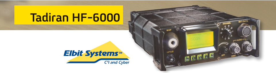
Well, I did some image search and found that the used device is the Tadiran HF-6000 produced by the Israeli Elbit System (figure 5):

Fig. 5

Further research confirms Kazakhstan's interest in military radio equipment manufactured by Elbit [2].

A final consideration must be made regarding the way used for the transfer of the message, or at least for this message. In addition to the 8N1 framing, it's to notice the lack of a datalink protocol, ie the message is sent "as is" and not as an attachment to an email message (for example). This "direct" way of transferring files is easier to encounter in less sophisticated waveforms such as FSK.

https://disk.yandex.com/d/milANJHyYytBVg

(1) Individual Partnership Action Plans (IPAP) are plans developed between NATO and different countries which outline the objectives and the communication framework for dialogue and cooperation between both parties.

(2) Steppe Eagle exercises have been canceled for political reasons or due to unease on the part of Kazakhstan regarding the United States.Of course, there’s a more obvious reason that the Steppe Eagle exercises have not been held since the summer of 2019: the COVID-19 pandemic.
https://thediplomat.com/2022/02/.../steppe-eagle-exercise-will-no-longer-fly/

[1] https://www.alem-edu.kz/en/university/voenno-inzhenernyj-institut-radioele/
[2] https://en.tengrinews.kz/military/kazakhstan-bought-israeli-technologies-for-producing-7718/

17 August 2021

188-110A, D1 D2 patterns and interleaved blocks boundaries (hardware implementation)


As well as to have some fun with ICs, I wanted to implement a part of the 188-110 modem to definitively understand the relationship between the periodicity of its bit stream and the lengths of the scrambler/interleaver (as indeed already discussed in other blog posts). The "core" is the data sequence randomizing generator: a 12-bit LFSR (Linear Feed Shift Register) with the functional "one-to-many" configuration and described by the polynomyal x^12+x^6+x^4+x+1. I implemented that LFSR by using twelve D-type flip-flop and three XOR gates, plus three 8-bit serial-to-parallel shift registers to manage the LFSR initial state; its operation, and other 188-110A modem functions such as clock, symbols formation and scrambler, are controlled by an Arduino board. The part more strictly related to the circuit (logic and electronics) is illustrated in the second part of the post.

That set of wires & ICs works great and my tests mainly concerned the data rate of 2400 bps: at that speed the framing has a duration of  48-symbols: 32 symbols in the UnKnown data position followed by a 16 symbols in the Known data (probes) position. As expected, the period of the bit stream is 480-symbol/1440-bit length (ie 10 frames) and matches exactly  3 runs of the sequence randomizing generator (reset'd every 160 symbol): regardless of the interleaver block length (figure 1).

Fig. 1 - 1440-bit/480-symbol period of the Arduino bit stream

However, there is still an uncertainty about the length of one interleaver block (short or long), or, better, about how it is indicated.
According to MIL 188-110 Standard, when the two Known symbol patterns preceding the transmission of each new interleaver block are transmitted, the symbols of these two Known patterns shall be set to Dl and D2 values, respectively, as defined in table XV of the standard. These two particular symbol patterns are indicated in figures 2,3 respectively for a real-world signal and the Arduino signal (both are 2400bps/Short).

Fig. 2 - D1 D2 patterns in a real-world bit stream

Fig. 3 - D1 D2 patterns in the Arduino bit stream

As you may check, each three rows the patterns of the last two probes exhibit the discontinuity due to the D1 and D2 values: therefore, since that three rows of the 480-symbols period contain 3×10 = 30 frames, the block length consists of 30×32 = 960 tribit symbols for the short interleave setting. The measured value is in constrast with what indicated in the standard; indeed, quoting MIL 188-110B #5.3.2.3.7.1.2,  "[...] The block length shall be 1440 tribit channel symbols for short interleave setting and 11520 tribit channels symbols for the long interleave setting".
You will get 1440 symbols if you consider also the probe symbols, ie if you compute 30×48 instead of 30×32... but the probe symbols are not interleaved, ie they are not fetched from the interleaver matrix! On the other hand, the short interleaver matrix for 2400 bps consists of 40 rows and 72 columns, ie 2880 bit that just will form 960 tribit symbols: this way, one interleaver block coincides with the dimensions of the correspondent intereleaver matrix. A similar calculation can be verified for the long interleave settings.

So, in my opinion, it seems that when 188-110 Sandard talks about the length of one interleaver block, it refers to all(!) the bit that compose UnKnown and Kown data symbols (indeed it talk generically of "channel" symbols) and not to the bit which are actually fetched from the interleaver matrix and that consequently will be used to form the UnKnown data symbols only (as it would seem more logical to me).

Notice that if the sequence randomizing generator is reset to 0xBAD after 80 transmit symbols, the resulting bit stream is 240-symbol/720-bit length (5 frames), ie just the half of the normal operations (as expected!).  

Fig. 4 - 720-bit period (LFSR reset'd after 80 transmit symbols)

Arduino part
As said above, the sequence randomizing generator is a 12-bit LFSR that I implemented by using 12 D-type flip-flops (6 x 74HC74) and 3 XOR gates (74HC86) used for the feedback path. Since the LFSR shall be preload to the initial seed 0xBAD (101110101101), we need to control the async set/reset inputs of the 12 flip-flops, therefore we need to manage 24 pins from the Arduino board and probably we do not have such number of ports available on the board. The idea is to use a serial-in parallel-out shift register (74HC595) to control 8 lines at a time, so link three registers together will give us the chance to get 24 parallel lines by sending 3 bytes on a serial pin of the Arduino board; that way, each 8-bit shift register will drive the set/reset inputs of four flip-flops (figure 5).

Fig. 5 -  three 8-bit shift register used to manage twelve D-type flip-flop

The connections for wiring the preload part are shown in figure 6

Fig. 6
188-110 Standard suggests to implement the sequence randomizing generator using a 12-bit LFSR in the "one-to-many" configuration, ie the most-significant bit is fed back directly into the least significant bit, and is also individually XORed with the other bits 6,4,1 (below in Figure 5). The connections for wiring are shown in figure 7.
Fig. 7
 
The Arduino "sketch" (the software) can be downloadeed from:
https://disk.yandex.com/d/TJvzhdThgCwClA

74HC74 is a dual positive edge triggered D-type flip-flop with individual data (nD), clock (nCP) inputs and asynchronous set (nSD) and reset (nRD) inputs.

74HC86 is a quad 2-input EXCLUSIVE-OR gate. 

74HC595 is an 8-bit serial-in/serial or parallel-out shift register with a storage register and 3-state outputs. Both the shift and storage register have separate clocks. The device features a serial input (DS) and a serial output (Q7S) to enable cascading.

pinning of the used ICs

Hardware (Arduino + breadboard) and software implement the red-circled parts of the 188-110A modem:


19 July 2021

tools to generate 188-110A channel probes... and not only them

I recently checked the 188-110A transmissions - referred to in this post - characterized by a secondary protocol not (yet) identified, the purpose was to verify if in the meantime some novelties had intervened such to shed a more light on the protocol itself: the attempt, however, was unsuccessful... though I paid more attention to the 188-110A channel probes patterns. After demodulating the signal, he channel probes do not show regular (known) patterns as instead it should happen, according to what is indicated in the documentation and looking at a synthesized waveform (figure 1).

Fig. 1 - synthesized and real-world 188-110A 2400bps

During the periods where channel probe symbols are to be transmitted, the channel symbol formation output is set to 0 (000) except for the two known symbol patterns D1 and D2 preceding the transmission of each new interleaved block. The symbol formation output is then scrambled  with the three bits supplied by the  randomizing generator,  a 12 bit shift register with the functional configuration shown on figure 2.
The shift register is pre-loaded with the initial pattern 101110101101 or 0xBAD and advanced eight times. Since after 160 transmit symbols the shift register is reset, each 480 transmist symbols the scrambler will produce the same ten patterns for the 16-symbols channel probes. 

Fig. 2 - 188-110A randomizing generator

As you can see, the patterns are so alternating that it looks like an artificial "variation", even if this "effect" is due to poor signal reception (mostly fading). The bitstream of figure 1 are obtained at the output of a generic PSK8 demodulator (SA), so I don't know exactly how a specific demodulator for 188-110A reacts to such sequences of the channel probes; probably it does not lose the synchronism ... even if some doubts arise about the exact demodulation of the signal (thank goodness that FEC exists). 

However, I have decided to spend some time examining the sequences generated by this circuit. As shown in figure 2, the randomizing generator implementation is a x^12+x^6+x^4+x+1 LFSR which is converted into its "one-to-many" counterpart, ie the most-significant bit is fed back directly into the least significant bit, and is also individually XORed with the other bits 6,4,1. Notice that using this style means that there is never more than one level of combinational logic in the feedback path, irrespective of the number of taps being employed in the traditional "many-to-one" implementation (increasing the levels of logic in the combinational feedback path can negatively impact the maximum clocking frequency).
At first I used two excellent "software" simulators: the first for PC - LFSR testbench, figure 3 [1] - the second for Samsung android tablet - Logic Simulator pro, figure 4 [2]. As soon as possible - or as soon as I recover the missing components - I will try a hardware simulation using my Arduino board.

Fig. 3 - LFSR Testbench simulating the sequence randomizing generator

 
Fig. 4 - Logic Simulator PRO simulating the sequence randomizing generator

These two tools are very interesting and useful also for simulating LFSRs that are used for sync sequences or scramblers, give them a try.

[1] https://www.fpga4fun.com/files/LFSRTestbench.zip
[2] https://logic-circuit-simulator-pro.it.aptoide.com/app

1 July 2021

8N1 async operations

8N1 async operations using STANAG-4285 and 110A Serial modems (1200bps/S, 1200bps/L respectively) recorded on 6.9 MHz band, the first likely from Turkey. After the removal of the framings, the 8-bit streams are not in clear text and therefore (off-line) encrypted.

Fig. 1 - STANAG-4285 user data
 
Fig. 2 - 110A ST user data
 

https://disk.yandex.com/d/oYXY9Rh4c9dm8Q

26 June 2021

3G-HF "BW5 + 110A" combined waveform ...or just coincidence?


From 19 to 23 June I monitored interesting transmissions on 5091.5 KHz/USB that seem to use a kind of "combined" waveform which consists of FLSU BW5 waveform followed by 188-110A 300bps waveform. For what concerns the timing, the sendings occur each minute, they last about 31 seconds and are arranged in a way that resembles the circuit mode service of STANAG-4538. Starting from thursday 24, these broadcasts have not been repeated (at least until today).

Fig. 1 - ACFs  


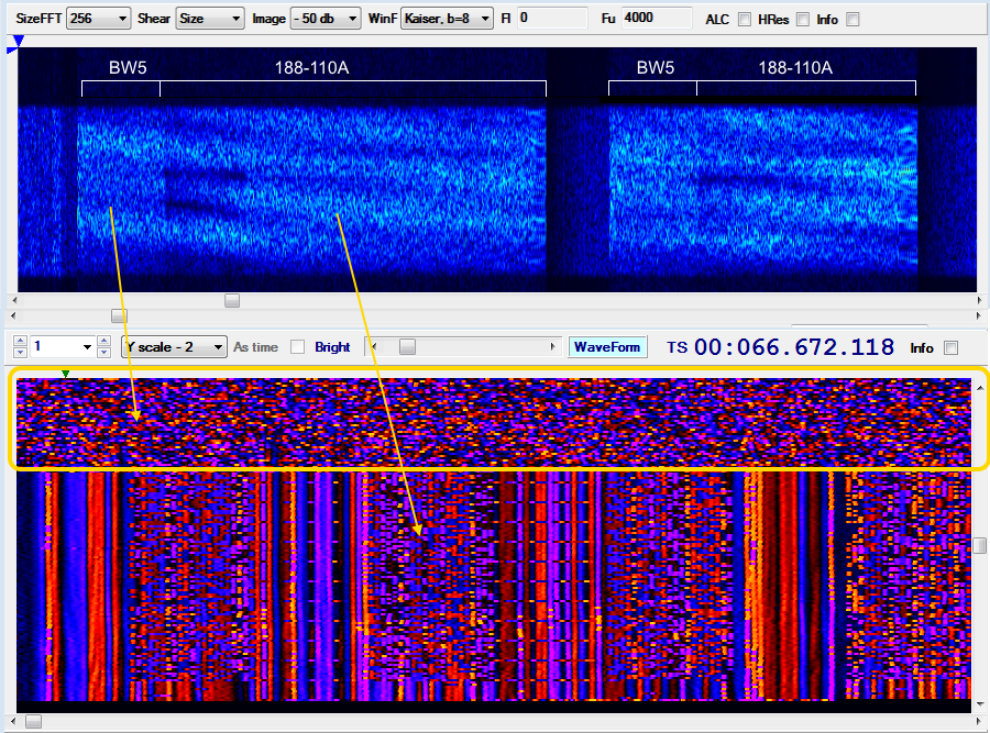
As said, it seems that the data are sent using a transmission composed of two parts: a sequence of FLSU PDUs, which are transmitted using the BW5 burst waveform, and the payload data, transmitted using the 188-110A serial waveform. These two parts are transmitted contiguously with no dead time separating them (Figure 2).

Fig. 2 - framing

That kind of waveform (BW5 + 110A) is indeed very odd, unless I have been mistaken and it is an overlapping of two distinct transmissions... but it would still odd that the overlapping be so perfect and continuous for more than two days.  Anyway, if it's a real "combined" waveform then it's definitely a synthesized waveform (SDR).
For clarity - however - it must be said that:
a) BW5 waveform (and thus the FLSU protocol) has been detected by the examination of the signal's ACF and its payload;
b) the length (duration) of the initial BW5 sequence finds a clarification in this post;
c) BW5 waveform could also be used to transport other types of PDUs and not only the PDUs of the FSLU protocol.

data link protocol
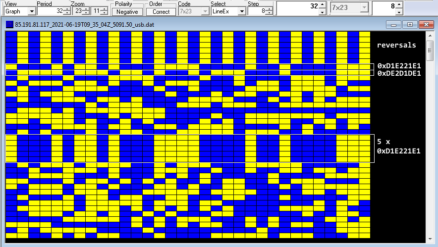
The used data link protocol is also interesting: its initial structure consists of 32-bit (4 bytes) patterns which are common to all the payloads (Fig. 3):

192-bit idle sequences of reversals (alternating sequences of '0's and '1's)
10001011010001111000010010000111 (0xD1E221E1) sequence #1
01111011101101001011100010000111 (0xDE2D1DE1) sequence #2
11 bytes length data block
10001011010001111000010010000111
10001011010001111000010010000111

10001011010001111000010010000111 (5 x sequence #1)
10001011010001111000010010000111
10001011010001111000010010000111

(data block follows)

Fig. 3 - data link protocol after 188-110A removal

The two 4-byte sequences are not originated by polynomials and are likely used as sync patterns, although the five repetitions of the sequence #1 lead to think to an Initialization Vector; in my opinion, a such method could be risky in terms of security since the same IV sequence is used for all the forwarded messages (unless they are test transmissions and/or pseudo random traffic). Data blocks seem anyway encrypted.

Fig. 4 - details of the 32-bit structure of the data link protocol

The exact same structure and 32-bit sequences have already been detected in some recordings of 2018 (!): also in this case they were "plain" 188-110A transmissions forwarded in circuit mode service [4].

TDoA direction finding
The transmissions are fairly receivable only in the northern regions of Europe, more precisely I used KiwiSDRs in Norway and Denmark [1][2]: that's a sign that a low power transmitter is used or that they serve a local area. Just about the site of the transmitter,  all my direction findings point to a well-restricted area north from Oslo, Norway (Figure 5).

Fig. 5 - TDoA results

Norway has released an interactive map of all the military locations where it is forbidden to operate a drone [3]. All the markers indicate an area where it is illegal to take aerial photographs or video using a camera or any other type of sensors: in figure 6 I have cut out an area that more or less follows the area identified by the DF.

Fig. 6

remarks
Starting from June 22 the transmissions show a paradigm change, a bit more in line with the circuit service model of STANAG-4538: the structure of the used data-link protocol, anyway, remains unchanged. 

These transmissions raise several questions, the first being whether or not it is an experimental combined waveform (and therefore if they are test transmissions). It would also be interesting to identify the transmitter site with greater precision and - if anything - which data protocol is used.

https://disk.yandex.com/d/2I0bzM2nDShWGA
https://disk.yandex.com/d/kD-9y_TFkZoFqQ
https://disk.yandex.com/d/Bt2pIPxE-o6Udw

[1] LB3J SDR in Smøla, Norway http://77.223.174.203:8073/
[2] KiwiSDR by OZ1BFM in Vejby, DENMARK http://oz1bfm.proxy.kiwisdr.com:8073
[3] http://googlemapsmania.blogspot.com/2018/09/norways-secret-military-sites.html
[4]  https://i56578-swl.blogspot.com/2018/03/unid-32-bit-secondary-protocol.html