Showing posts with label P=32. Show all posts

23 March 2026

Decoding UFO-11 MILSATCOM Downlink (MIL-STD-188-181)

While monitoring the UHF band, my friend Kosmod successfully captured and shared a series of military satellite 2400 Bd bursts on 252.2525 and 253.6460 MHz. The signal displays BPSK modulation at 2400 Baud (or 2400 bps, given the 1 bit/symbol efficiency of BPSK).

Fig. 1: waveform analysis of the captured signals

The 253.646 MHz signal falls directly within the downlink range for UHF MILSATCOM. This specific frequency is part of the UFO (UHF Follow-On) and legacy FLTSATCOM constellations operated by the US Navy to provide global coverage for maritime and ground forces.
Technically, this is Channel 14 in the Navy's 'Bandplan Bravo'. While the nominal center is 253.650 MHz, these satellite transponders act as 'bent-pipes', simple relays that repeat the uplink signal across their available bandwidth. Because of this, seeing a signal centered at 253.646 MHz is perfectly normal; it's simply sitting on the lower edge of that 25 kHz wideband assignment.
Based on the location of Kosmod, UFO-11 (USA 174) (1) is the primary "workhorse" for this region. These satellites utilize Global Beams; for instance, a satellite parked at 75°E and at a geostationary altitude of 35,786 km (like UFO-11) covers everything from Central Europe all the way to Western China.

Looking at the differential decoded bitstreams (Figure 2), we are looking at a classic Satellite Military Communication (SATMILCOMM) frame structure. These patterns are highly characteristic of bursts sent over tactical waveforms (like MIL-STD-188-181 or similar UHF SATCOM standards).

Fig. 2 : differential decoded bitstreams

Here is a proposed breakdown of what those specific hex blocks could represent:

1. The Preamble (AA AA AA AA ...)
This is the Bit Synchronization sequence. Purpose: In binary, AA is 10101010. This alternating pattern of ones and zeros allows the receiver's modem to "lock on" to the clock frequency of the transmission.

2. The Sync Word / Frame Marker
The block starting with 46 8B 87 84... is the Frame Synchronization Word. Notice that this block is identical in all three headers. Once the receiver has the timing (from the AAs), it looks for this specific unique bit string to know exactly where the "data" actually begins. It marks the boundary between the "noise/tuning" and the actual message.

3. The Metadata / Packet Header (The Variable Block)
This is the most interesting part. Notice that this section changes in every capture. This block typically contains the Control Channel information. In military protocols, this often includes: Destination/Source IDs, Initialization Vector (IV), Message Length/Type.

4. The Flush / Transition Pattern (8B 87 84 7B ...)
You see this repeating sequence just before the encrypted payload. This acts as a pad or transition gap. It ensures the receiver's hardware buffer is ready and that the cryptographic resync has occurred before the high-entropy (encrypted) data hits the stream. The fact that it repeats exactly five times suggests a fixed-length buffer requirement for the specific radio hardware being used.

A note on the "Encrypted Data": because the data following these headers is encrypted (likely using AES-256 or a sovereign military grade equivalent), it will appear as completely random noise with no repeating patterns. Without the specific cryptographic key and the correct algorithm, that portion cannot be decoded.

The captured transmission is almost certainly not the classic Fleet Broadcast beacon, but rather a more active DAMA/IW Control Channel:
* Fleet Broadcast (Beacons) are usually found at the "low end" of the UFO band (e.g., 250.350 MHz to 250.650 MHz) and they are constant, 24/7 transmissions
* Tactical Data Links (Your Signal) sits in the "Tactical" portion of the bandplan. This area is reserved for Demand Assigned Multiple Access (DAMA) and Integrated Waveform (IW). These channels don't just broadcast one-way; they manage a "conversation" between the satellite and hundreds of ground terminals.

It is interesting to note the parallels with an HF signal captured previously on 7961 kHz (USB): a 3G-HF STANAG-4538 transmission. The demodulated bitstreams exhibit a series of data blocks characterized by a 32-bit framing structure, primarily due to the fixed length of their headers [1].

 https://disk.yandex.com/d/3b9hpOGFoZkp6g

(1) Satellite Profile: UFO-11
NORAD ID: 28117
Current Position (March 2026): It is stationed in a geostationary orbit over the Indian Ocean, currently hovering around 75° East longitude. Coverage: This position provides a massive footprint that covers almost all of Russia (except the extreme Far East), the Middle East, Eastern Europe, and Africa. Inclination: As of 2026, UFO-11 has an orbital inclination of approximately 8.5° to 9°. This means it is no longer perfectly stationary; it appears to drift North and South in the sky over a 24-hour period.
UFO-11 was the final satellite in the UFO series and includes the most advanced digital processing of the bunch.

Communications Payload (The "Bent-Pipe" Hardware)
UHF Channels: 39 Channels (Total), voice and Low-speed data
Wideband: 21 Channels @ 25 kHz used for DAMA/IW
Narrowband: 17 Channels @ 5 kHz    used for legacy tactical teletype/secure voice
Anti-Jam: FHSS (Frequency Hopping), protection for the Fleet Broadcast (FLTSAT)
GBS Payload: 4 Transponders (Ka-Band), high-speed Global Broadcast Service (video/maps).

Signal Technical Specifications
Modulation: BPSK / SBPSK
Symbol Rate: 2400 Baud    
Protocol Standard: MIL-STD-188-181C The "Integrated Waveform" (IW) standard. It governs how the satellite manages multiple users in a single 25 kHz channel.
Frame Structure: TDMA Burst Time Division Multiple Access. The signal consists of a Preamble, a 160-bit Unique Word, a Control Header, and the 5-fold redundant Trailer

[1] https://i56578-swl.blogspot.com/2018/03/unid-32-bit-secondary-protocol.html

4 December 2024

256-bit IVs & 0xD1E221E1 sequence

Just a quick note to observe that bitstreams using (alleged) 256-bit Initialization Vectors (IV) encryption have the same 32-bit/4-byte sequence repeated three times. For example, in the bitstream in Figure 1 (MS-110A transmission) you can clearly see the 256-bit IV sequences, each repeated eight times. 

Fig. 1

But if you reshape the same bitstream into columns of 32 bits the same 32-bit sequence 0xD1E221E1 emerges (Figure 2).

Fig. 2

I have previously encountered bitstreams with 256-bit IVs [1] but at that time I had not investigated further, focusing only on those sequences. As a counter-proof, I took back and analyzed those signals and - surprise - they also all present the same sequence 0xD1E221E1 after the IVs (Figure 3).

Fig. 3

It should also be said that I have also encountered the sequence 0xD1E221E1 three times previously [2] but, when I re-analyzed those transmissions, the 256-bit IVs were not found (Figure 4).
 
Fig. 4

Both for the position of the 4-byte string 0xD1E221E1 (after or WITHOUT the alleged IVs) and for its presence in different streams it is difficult to say whether it identifies a sync string for a cipher device or whether it identifies a particular datalink protocol. However, in all cases I could analyze, STANAG-4538 (3G-HF) "circuit mode service" is used along with MS-110A as the traffic waveform.
Comments and suggestions on this matter are welcome!
 

[1] https://i56578-swl.blogspot.com/2020/09/s-4538110a-transmissions-using-unid-256.html
[2] http://i56578-swl.blogspot.com/search/label/P%3D32

26 August 2024

about the unid 32-bit protocol used in S-4538 + MS-110A transfers

This is the third time I have encountered these transmissions [1] and, given the good number of recordings made over a few days on the frequency 6964.5 KHz/USB, it is now possible to draw a more definitive "picture".

Transmissions normally occur each 5 minutes and last 1.5 - 2 minutes average. STANAG-4538 (3G-HF) "circuit mode service" is used, where MS-110A (usually in 75bps/Long Interleaver mode) is the used traffic waveform; sometimes a transmission may consist of two or more distinct data transfer sessions (Figure 1).

Links are established using the FLSU (Fast Link SetUp) Asynchronous scanning call, using BW5 and an "optimized" waveform which provides no repetition of the initial TLC section (used for transmitter level control and receiver AGC settling). Such a scanning call is exactly described in paragraph C.5.2.4.5.2 of  MIL 188-141B Appendix C: "The LE_Scanning_Call PDU shall be sent repeatedly to capture scanning receivers [...] During a scanning call, only the first LE_Scanning_Call PDU shall include TLC. All succeeding LE_Scanning_Call PDUs and the LE_Call PDU shall omit TLC, and include only the BW0 preamble and data portions" (1)(2). So, we look at a STANAG-4538 FLSU Async call (since the use of BW5 waveform) which is 188-141B compliant for what regards its formation (since the omission of  the TLC sections): ie, a sort of  188-141B/STANAG-4538 mixed implementation most likely implemented by L3Harris [2][3]. That "formation" of the Async call clarifies why decoders recognize only the "first" BW5 PDU. 

Fig. 1

Looking at the asynchronous scan calls, at first glance it seems that Linking Protection (LP) is not used: in fact, as you can see, the decoded strings are identical. This should not happen since when operating in encrypt mode, the LP algorithm takes as inputs the PDU to be scrambled, a key variable, and a “seed” that contains Time of Day (TOD) and the frequency that carries the protected transmission.

2024-08-21T09_54_32Z BW-5 00111001010000100011011001001010011110001000011010
2024-08-21T09_56_17Z BW-5 00111001010000100011011001001010011110001000011010
2024-08-21T10_01_54Z BW-5 00111001010000100011011001001010011110001000011010

2024-08-22T07_46_52Z BW-5 00010110100000110011111110111010101110111100000110
2024-08-22T07_51_52Z BW-5 00010110100000110011111110111010101110111100000110

Anyway, it's to note that when the protection against spoofing offered by LP is not required, LP may be used without a key variable or seed to provide only scrambling based on the network number as described in STANAG-4538 4.1.2 (in this regard, note that the scanning calls of 2024-08-22, for example, do not have the expected value "001" in the first three bits). 

The analysis of the MS-110A decoded bitstreams show initial 100 bytes length headers which have some parts common to all the bitstreams, the header "format" is more evident after the removal of the initial "10"s sequence (Figures 2,3).

Fig. 2

Fig. 3

In my opinion, headers are made up of the following structure (Figure 4):

1) common initial sequence

1100000100011100101001 (maybe 001100000100011100101001, 0x0CE294)

2) common 193 bits length "01"s sequence, (phasing?). Boundaries are marked by two consecutive logical "1"

3) common 160 bits / 20 bytes length sequence (sync sequence for the receive crypto device?)

10001011010001111000010010000111
01111011101101001011100010000111
01000100011110000100100001110111
10111011010010111000101101110100
01000111100001001000011101111011

4) 256 bits / 32 bytes length sequence which is different in every bitstream (Initialization Vector?)

5) common 5×32 bits / 4 bytes repeated sequence (frame sync?). Note that the sequence can't be an Initialization Vector since it's always the same in every bitstream.

10001011010001111000010010000111
10001011010001111000010010000111
10001011010001111000010010000111
10001011010001111000010010000111
10001011010001111000010010000111


Also note that the 4 bytes repeated sequence is used in the first 4 bytes of the 160 bits sequence.

Fig. 4 - the common blocks in the headers of the bitstreams

According to the results of the "Shannon Entropy" and "Statistical" tests, the ansferred data are most probably encrypted (Figure 5).
The measure of the Shannon Entropy can be used, in a broad sense, to detect whether data is likely to be structured or unstructured. 8 is the maximum, representing highly unstructured, 'random' data. Properly encrypted or compressed data should have an entropy of over 7.5 The statistical test below determines the randomness, the number of single bits in the stream is counted, then the double bits, then the triple bits and so on to the end. The result is a graph: if the information is not systematic, the adjacent columns should be half the size of the previous ones. Both the test shows good encryption quality.

Fig. 5 - Shannon Entropy and Statistical tests on the data portions

The transmissions are fairly receivable only in the northern regions of Europe, likely a low power transmitter is used or a local/domestic area shall be served. Just about the site of the transmitter,  all my direction finding attempts point to a quite large area in Norway (Figure 6): maybe a Royal Norwegian Navy Tx? Anyway, it's to notice that the DF results "suffer" from the lack of detection points west of Norway.

Fig. 6 - Direction finding attempts (TDoA algorithm)

Monitoring & recordings thanks to the remote KiwiSDRs SM0KOT (Sweden) and OZ1AEF (Denmark) [4][5]. 

https://disk.yandex.com/d/AcwncUTKxXlQ_A (decoded bitstreams)

(1) MIL 188-141B refers to BW0 as the waveform to convey "LE_Scanning_Call PDU" and "LE_Call PDU" (LE stands for Link Establishment): FLSU, and consequently the BW5 waveform, were not yet defined at that time.

(2) 188-141B (released on March 1999!) was superseded by 188-141C (December 2011), in its turn superseded by 188-141D (December 2017): the last two standards no longer have the Appendix C but only some short paragraphs, among them the #C.6 says "The specifications previously contained in this appendix have been replaced with reference to the essentially identical NATO STANAG 4538".

[1] http://i56578-swl.blogspot.com/search/label/P%3D32
[2] http://i56578-swl.blogspot.com/2022/10/harris-3g-ale-flsu-async-call.html
[3] http://i56578-swl.blogspot.com/2022/10/harris-3g-ale-flsu-async-call-2.html
[4] http://aspliden.kostet.se:8074/
[5] http://85.191.35.22:8073/


26 June 2021

3G-HF "BW5 + 110A" combined waveform ...or just coincidence?


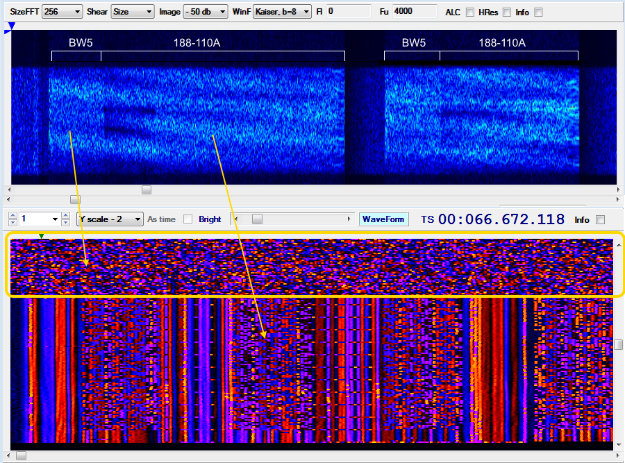
From 19 to 23 June I monitored interesting transmissions on 5091.5 KHz/USB that seem to use a kind of "combined" waveform which consists of FLSU BW5 waveform followed by 188-110A 300bps waveform. For what concerns the timing, the sendings occur each minute, they last about 31 seconds and are arranged in a way that resembles the circuit mode service of STANAG-4538. Starting from thursday 24, these broadcasts have not been repeated (at least until today).

Fig. 1 - ACFs  


As said, it seems that the data are sent using a transmission composed of two parts: a sequence of FLSU PDUs, which are transmitted using the BW5 burst waveform, and the payload data, transmitted using the 188-110A serial waveform. These two parts are transmitted contiguously with no dead time separating them (Figure 2).

Fig. 2 - framing

That kind of waveform (BW5 + 110A) is indeed very odd, unless I have been mistaken and it is an overlapping of two distinct transmissions... but it would still odd that the overlapping be so perfect and continuous for more than two days.  Anyway, if it's a real "combined" waveform then it's definitely a synthesized waveform (SDR).
For clarity - however - it must be said that:
a) BW5 waveform (and thus the FLSU protocol) has been detected by the examination of the signal's ACF and its payload;
b) the length (duration) of the initial BW5 sequence finds a clarification in this post;
c) BW5 waveform could also be used to transport other types of PDUs and not only the PDUs of the FSLU protocol.

data link protocol
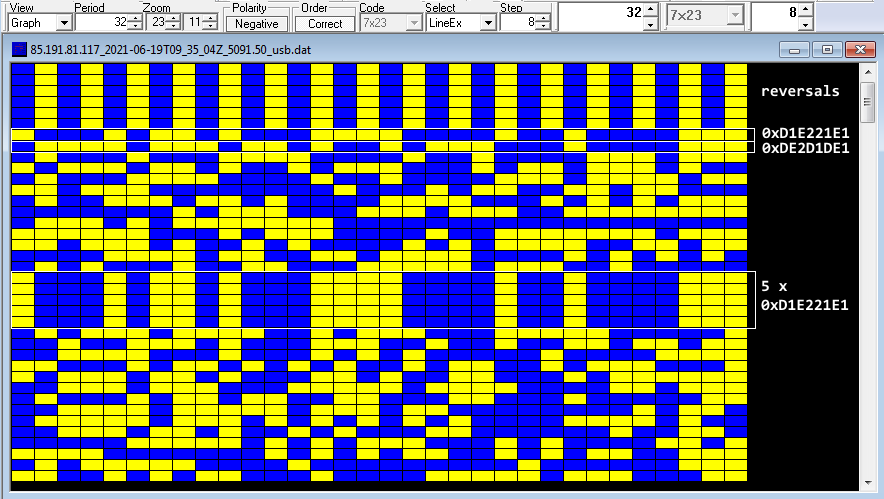
The used data link protocol is also interesting: its initial structure consists of 32-bit (4 bytes) patterns which are common to all the payloads (Fig. 3):

192-bit idle sequences of reversals (alternating sequences of '0's and '1's)
10001011010001111000010010000111 (0xD1E221E1) sequence #1
01111011101101001011100010000111 (0xDE2D1DE1) sequence #2
11 bytes length data block
10001011010001111000010010000111
10001011010001111000010010000111

10001011010001111000010010000111 (5 x sequence #1)
10001011010001111000010010000111
10001011010001111000010010000111

(data block follows)

Fig. 3 - data link protocol after 188-110A removal

The two 4-byte sequences are not originated by polynomials and are likely used as sync patterns, although the five repetitions of the sequence #1 lead to think to an Initialization Vector; in my opinion, a such method could be risky in terms of security since the same IV sequence is used for all the forwarded messages (unless they are test transmissions and/or pseudo random traffic). Data blocks seem anyway encrypted.

Fig. 4 - details of the 32-bit structure of the data link protocol

The exact same structure and 32-bit sequences have already been detected in some recordings of 2018 (!): also in this case they were "plain" 188-110A transmissions forwarded in circuit mode service [4].

TDoA direction finding
The transmissions are fairly receivable only in the northern regions of Europe, more precisely I used KiwiSDRs in Norway and Denmark [1][2]: that's a sign that a low power transmitter is used or that they serve a local area. Just about the site of the transmitter,  all my direction findings point to a well-restricted area north from Oslo, Norway (Figure 5).

Fig. 5 - TDoA results

Norway has released an interactive map of all the military locations where it is forbidden to operate a drone [3]. All the markers indicate an area where it is illegal to take aerial photographs or video using a camera or any other type of sensors: in figure 6 I have cut out an area that more or less follows the area identified by the DF.

Fig. 6

remarks
Starting from June 22 the transmissions show a paradigm change, a bit more in line with the circuit service model of STANAG-4538: the structure of the used data-link protocol, anyway, remains unchanged. 

These transmissions raise several questions, the first being whether or not it is an experimental combined waveform (and therefore if they are test transmissions). It would also be interesting to identify the transmitter site with greater precision and - if anything - which data protocol is used.

https://disk.yandex.com/d/2I0bzM2nDShWGA
https://disk.yandex.com/d/kD-9y_TFkZoFqQ
https://disk.yandex.com/d/Bt2pIPxE-o6Udw

[1] LB3J SDR in Smøla, Norway http://77.223.174.203:8073/
[2] KiwiSDR by OZ1BFM in Vejby, DENMARK http://oz1bfm.proxy.kiwisdr.com:8073
[3] http://googlemapsmania.blogspot.com/2018/09/norways-secret-military-sites.html
[4]  https://i56578-swl.blogspot.com/2018/03/unid-32-bit-secondary-protocol.html

16 March 2018

unid 32-bit secondary protocol

The analysis is related to a 3G-HF STANAG-4538 transmission in which the traffic service is “Circuit Mode” and spotted on 7961 KHz/USB, 188-110A Serial is used as the traffic waveform. After demodulation of 188-110A, the stream obtained shows a series of data blocks, corresponding to the transmitted bursts, characterized by a 32-bit length period which is due to the headers of each block (Fig. 1). Comparing the headers gives a common structure of 120 bytes that differs by 32 bytes (Fig. 2).

Fig. 1 

Fig. 2