Showing posts with label LINK-11 CLEW. Show all posts

10 August 2018

LINK-11 CLEW, doubts about the generator polynomial x^5+x+1

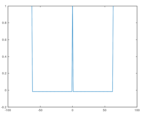
I have some doubts about the description at page 19 of MIL 188-203-1A (Tadil-A/Link-11) [1]: the document states that the Start Code and the Address Code frames " [...] are equivalent to 60-bit portions of the maximum-length shift register sequence with generator polynomial G(x) =  x5+x+1" ...but such a fifth grade polinomyal has a maximum length sequence (MLS) of 31 bits (25-1). Indeed, I found the generator polymonial x6+x+1, whose MLS is 63, for both start and address frames:
 
111100101000110000100000111111
101100110111011010010011100010
100001000001111110101011001101
110100100111000101111001010001

Using a GNU Octave script [2] I also checked the three fundamental properties of LFSR maximum length sequences: Balance Property, Runlength Property, and Autocorrelation Property [3]: verification fails for x5+x+1

  • The Code does NOT satisfy Balance Property: number of 1s and 0s are 17 14
  • The code does NOT satisfy RUN LENGTH property: the run length is 10    2    1    1    2
  • The Code does NOT satisfy the Autocorrelation Property

  while verification is ok for x6+x+1 
  • The Code satisfies Balance Property: number of 1s and 0s are 32 31
  • The code satisfies RUN LENGTH property: the run length is 16    8    4    2    1    1
  • The Code satisfies the Autocorrelation Property


So I do not know if I'm wrong or if there's a typo in 188-203-1A, comments are welcome.

4 August 2018

LINK-11 CLEW, Hamming check matrix

The check of a Link-11 CLEW stream discussed in the end part of this post, can be speed up by using the Hamming parity check matrix for the H(30,24) coding, ie a 30-bit code word consisting of 24 bits for data + 6 bits for Hamming parity bits (termed EDAC in Link-11 literature). The check matrix is constructed as shown in MIL 188-203-1A #5.2.4.1 and here.

 
Code verification is carried out by comparing each line of code in turn with all rows of the parity check matrix, except the extra parity line (the overall parity bit): the vertical correspondences of the "1" locations in the code line and in the row #n of the check sub matrix are counted. If the matches are even then the correspondent location #n in the EDAC bits will be "1", otherwhise (ie matches are a odd number) will be "0" (odd parity).
 
 
  EDAC           data
110100 000001110101110001100010
010011 111001110010010001111011
110100 111100101110010110011111
100100 010111010000110110000110
010010 011010000000010100100111
110001 010001110110000010010000

     check sub-matrix           identity sub-matrix
111111111111100000000000 010000
111111000000011111110000 001000
110000111100011110001110 000100
001100110011011001101101 000010
101010101010110101011011 000001
111111111111111111111111 111111
Test the first line of code 000001110101110001100010

000001110101110001100010
111111111111100000000000 check matrix line #0
6 matches, EDAC bit #0 shall be 1

000001110101110001100010
111111000000011111110000 check matrix line #1
4 matches, EDAC bit #1 shall be 1

000001110101110001100010
110000111100011110001110 check matrix line #2
5 matches, EDAC bit #2 shall be 0

000001110101110001100010
001100110011011001101101 check matrix line #3
6 matches, EDAC bit #3 shall be 1

000001110101110001100010
101010101010110101011011 check matrix line #4   
5 matches, EDAC bit #4 shall be 0
EDAC bits 0-4: 11010

Test the second line of code 111001110010010001111011

111001110010010001111011
111111111111100000000000 check matrix line #0
7 matches, EDAC bit #0 shall be 0

111001110010010001111011
111111000000011111110000 check matrix line #1
8 matches, EDAC bit #1 shall be 1

111001110010010001111011
110000111100011110001110 check matrix line #2
7 matches, EDAC bit #2 shall be 0

111001110010010001111011
001100110011011001101101 check matrix line #3
9 matches, EDAC bit #3 shall be 0

111001110010010001111011
101010101010110101011011 check matrix line #4   
10 matches, EDAC bit #4 shall be 1

EDAC bits 0-4: 01001
The verification of the remaining combinations confirms the use of the same method of checking (if you want, you can check it yourself).

If only one error is detected, it is corrected and sent to the computer. The computer is also advised that the word contained an error and that it is corrected. If two errors are detected the Hamming decoding can only determine that errors exist but cannot determine which bits are in error.

16 July 2018

LINK-11 CLEW, conventional waveform


The 16 tone frequencies used by CLEW are 605 Hz (used for Doppler correction), 2915 Hz (used for data and synchronization) and 935, 1045, 1155, 1265, 1375, 1485, 1705, 1815, 1925, 2035, 2145, 2255, and 2365 Hz. All information is conveyed by DQPSK modulation at symbol rate of 75 or 45.45 Baud of the 15 data subcarriers tones (Doppler tone remains unmodulated), each of the tone represents 2 data bits and then resulting in a total of 30 data bits consisting of Control Code frames and Data Message frames(M-series messages). The tone at 935 Hz corresponds to bit locations 0 and 1, last tone at 2915 corresponds to bit locations 28 and 29.
Sometimes you may see CLEW using simultaneously the USB and LSB (ISB): indeed, identical signals are transmitted on in ISB and at the receiver both the sidebands will be separately and independently deodulated.  A means is provided to allow operator selection of USB, LSB or the diversity operation (DIV) modes:
  • DIV: data words derived from the diversity combination of the USB and LSB will be provided to the tactical computer. This mode of operation is used to help combat multipath interference.
  • Automatic: the receiving station automatically selects the version that represents the best information available from the USB, LSB or DIV version of the received data word.
When the criteria do not establish a clear choice, the DIV version is selected.  

The three control codes which are used to operate a Link-11 net are the Start Code, Stop Code, and Address Code, each consisting of two encoded 30-bit frames. The Start Code is the first two frames of the transmitted data message while the two frames Stop Code immediately follows the last message frame to signify the end of the data. There are two stop codes according to the transmitting station: Control Stop Code (transmission from the data net control station, or DNCS) is a 2 frames consisting of all "zeros", and Picket Stop Code (transmission from a picket station) which consists of a 2 frames consisting of all "ones". 
The Start Code is the first two frames of the transmitted data message while the two frames Stop Code immediately follows the last message frame to signify the end of the data. There are two unique stop codes according to the transmitting station:
  • Control Stop Code (transmission from the data net control station, or DNCS) is a 2 frames consisting of all "zeros",
  • Picket Stop Code (transmission from a picket station) is a 2 frames consisting of all "ones".
Each net partecipating unit is identified by the Address Code which immediately follows the Control Stop Code if the DNCS transmits data.

Fig. 1 - Link-11 data segment
The Data Message frames (Figure 2) follow the Start Code and contain tactical information. Each Data Message frame consists of 30 bits composed of a 24-bit word provided by the tactical computer and 6 Hamming parity bits (bit locations 24 through 29) provided by the modem. The Hamming parity bits are used by the receiver modem for error detection and correction, for this reason they are also refferred to as EDAC bits. Only Data Messages contain Hamming parity bits: Start, Stop, and Address codes are not Hamming parity encoded.
Notice that the 24-bit words may be optionally encrypted using KG-40 crypto device which just sits in midlle between tactical computer and modem. 

Fig. 2 - Link-11 Data Message frames
The six EDAC bits are encoded as follows:
  • Bit 29 is set such that when added to bits locations in 11 through 23, the number of ones will be an odd number;
  • Bit 28 is set such that when added to bits locations in 4 through 10 and 18 through 23, the number of ones will be an odd number;
  • Bit 27 is set such that when added to bits in locations 1,2,3,7,8,9,10,14,15,16,17,22, and 23, the number of ones will be an odd number;
  • Bit 26 is set such that when added to bits in locations 0,2,3,5,6,9,10,12,13,16,17,20, and 21, the number of ones will be an odd number;
  • Bit 25 is set such that when added to bits in locations 0,1,3,4,6,8,10,11,13,15,17,19,21, and 23,the number of ones will be an odd number;
  • Bit 24 is set such that when all the bits of the frame are added, the number of ones will be an odd number. Bit 24 is called the overall parity bit. 
Figure 3 shows a check of the first six 30-bit frames of the Data Message in Fig.2

Fig. 3