19 November 2016

R&S proprietary ARQ-protocol RSX.25 over GM-2100 HF modem


transmission received on 06450.0 KHz on USB at 0753 UTC. The ending part in MIL 188-141A, which terminates the link, reveals that the user is the Italian "Guardia di Finanza - GdF", ALE addresses are CAGLIARI (Coastal Naval Station in Cagliari, the sender) and the patrol boat OLTRAMONTI (the receive peer). 
Data are sent using the HF waveform "Signal Format", a so-called Rohde & Schwarz proprietary advanced waveform originated by the HF modem GM2x00, in combination with the proprietary ARQ-protocol RSX.25. LAN/WAN interconnections are most likely managed by the "Message Handling System PostMan" running at upper layer.
RSX.25 literally stands for R&S adaptation of wired X.25 protocol to the HF radio channel, it derives from the packet protocol X.25 and cannot be used togheter with STANAG and MIL-STD HF waveforms such as S-4039, S-4285 and 199-110A; for these waveforms, radio protocols such as STANAG 5066 are available (quoting from R&S data sheets [1]).

The GM2x00 waveform "Signal Format" exhibits the usual 1800Hz carrier with PSK-8 modulation at 2400 symbols/sec (Fig. 1)

Fig.1
Figs. 2a and 2b show the frame structure. The preamble consisting of a fixed 192 symbol sequence enables the receive station to synchronize with correct timing and phase. The following data block consists of 64-symbols frames each composed of 48 unknown (data) symbols + 16 known symbols (probe). The postamble, terminating the data block, has a structure which is basically the same as that of the data frames but it contains a stop-code sequence instead of information data.
Fig.2a
Fig. 2b (from a different recording)

Most likely the patterns of the test sequences generate the 133.33msec ACF spikes, i.e. five data blocks which make 960 bit or 320 symbols period (Fig.3).
 
Fig.3
The RSX.25 protocol permits all types of digital data to be transmitted, eg for a printer, digital camera, camcorder or fax unit. RSX.25 organizes the data to be transmitted in packets, which are successively transferred to the data modem. The packets contain a variable number of frames, the number per packet depending on radio-link quality and being adapted at regular intervals.
The data transmitted in a packet are distributed among the frames. The length of the frame data is variable and also depends on radio-link quality. In channels of very good quality, a frame contains 250 data bytes, in strongly disturbed channels 4 bytes. The length of the transmitted data is continually adapted to link quality

RSX.25 has a typical period of 8-bit period with recognizable patterns and is visible once removed the overhead due the Signal Format waveform (Fig. 4).

Fig.4

https://www.rohde-schwarz.com/fi/file/n160_email.pdf
https://www.rohde-schwarz.com/file/n155_shortwave.pdf


https://yadi.sk/d/L8ccg2Nnyq5Su

17 November 2016

cars, chameleons, networks, and other stories (update)

6231 net (6231.0 KHz)
I recently spotted the frequency 6231.0 KHz on USB where stations connect following the same procedure as of AB-net and use STANAG-5066 HMTP protocol which is transported by a STANAG-4285 modem configured for 1200 bps and short interleaver (Figs. 1,2).  As in the 5054-net, the message transfer is not preceded by ALE or selcall phase and this supports the idea of scheduled tansmissions. 
The post related to AB-net and 5054-net (HRV MORH-u) can be read here.

Fig.1 - the HF waveform (Stanag-4285)
Fig.2 - 1776 bit period (Stanag-5066)

While the transmissions in the AB-net are scheduled on tuesday and thursady from 0830 UTC (0730, daylight savings time), transmissions on this frequency start  at 0800 UTC on monday and wednesday (most likely 0700, daylight savings time)[1]. These are the heard callsigns,  listed in the call-order: 
GHU3 (net-control station)
ONI6
ZIO4
OLI7
NIK2
ULI6
VEL8
CIK5
ZIL7
Stations are contacted a first time by GHU3 for a radio-check then, in case of messages, the stations shall be contacted a second time and in the same order. Unless the initial 188-141 2G-ALE phase, the message transfer follows the schema seen here, used in the AB-net.

The HMTP headers in Fig. 4 prove that this net belongs to the HRV MORH-u network as the previous AB-net and 5054-net: same OS (Linux Open-SUSE), same STANAG-5066 application ("CroS 5066", developed by CROZ) and same attachment filename.

Fig. 4

The examination of the headers of the Data PDUs (D_PDU) gives the chance to get the STANAG-5066 addresses of the nodes in the play. The D_PDU headers can be highlighted by synchronizing the bitstream on the 16-bit Maury-Styles sequence 0xEB90 since all D_PDUs, regardless of type, begin with that same sync (it's just this sequence that causes the 1776-bit ACF of Figure 2).

Fig.5 - D_PDU headers
The S-5066 addresses obtained from the recordings belong to the 006.008.003.zzz subnet, then 5054.0 and 6321.0 KHz  are just two channels of the same subnet.
Below the updated S-5066 Addresses Table and the Network Map. 

AB-net 5838.0 KHz (...)
ALE  S-5066 Add.       E-mail Add. 
ABC7 006.008.001.039   user1@asdf.123 (ncs)
ABD1 006.008.004.166   user1@sdfg.123
ABG6 006.008.004.165   user1@dfgh.123
ABF2 006.008.006.226   user1@fghj.123
ABS5 006.008.008.215   user1@ghjk.123
ABK4 006.008.002.144   user1@jklp.123
ABH3 006.008.002.055          ?


5054/6231-net 5054.0 KHz, 6231.0 KHz
CALL S-5066 Add.       E-mail Add.
GHU3 006.008.004.165   user1@aysxd.111 (ncs)
ZIO4 006.008.003.032   user1@oli93.111
     006.008.003.033   user1@lost62.111

NIK2 006.008.003.036   user1@dres32.111
ULI6 006.008.003.037   user1@fejk8.111

CIK5 006.008.003.039   user1@huba9.111
ONI6
OLI7
VEL8
ZIL7


Anyway, these are tactical callsigns and rotate likely on a monthly base: e.g. in January 16 2017  the station user1@huba9.111 has been heard with callsign CHP3 (was CIK5) and obviously with same S-50966 Address (006.008.003.039).

[1] further recordings are needed

7 November 2016

STANAG-4538 3G-HF, HDL complete session


3G-HF HDL transfer heard on 10627.0 KHz/USB at 1258 UTC
The High-throughput Data Link protocol (HDL), defined in STANAG-4538, is a selective repeat ARQ protocol which can only be run in a point-to-point data packet connection. HDL is most efficient when large volumes of data are to be transmitted and the channel conditions are moderately good, while LDL is best suited for small data volumes and in poor quality channel
"Data transfer by HDL begins after the stations have already established the data link connection in the traffic setup phase (using FLSU BW5 waveform). In an HDL data transfer, the sending station and the receiving station alternate transmissions in the manner depicted in figure 1; the sending station transmitting HDL_DATA PDUs containing payload data packets, and the receiving station transmitting HDL_ACK PDUs containing acknowledgments of the data packets received without errors in the preceding HDL_DATA PDU. The end of a data transfer is reached when the sending station has transmitted HDL_DATA PDUs containing all of the payload data in the delivered datagram, and the receiving station has received these data without errors and has acknowledged their successful delivery. When the sending station receives an HDL_ACK PDU indicating that the entire contents of the datagram have been delivered successfully, it sends an HDL_EOM PDU repeated as many times as possible within the duration of an HDL_DATA PDU, starting at the time at which it would have otherwise transmitted the next HDL_DATA PDU." [1]

fig. 1a
Fig. 1b
 
As in STANAG-4538 Table 13-1, HDL protocol use the burst waveforms BW2 for data forward and BW1 for ACK and EOM/Term signal, all the burst waveforms use the basic PSK-8 modulation at 2400 baud centered at 1800hz also used in the MIL-STD 188-110A serial tone modem waveform (fig. 2) and can be identified by measuring their duration (fig. 3)

fig. 2
fig. 3
BW2 consists of 100 msec TLC section and a short (26,67 msec) preamble followed by a number of fixed-size data packets (3, 6, 12, or 24): the number of packets is negotiated before the HDL protocol starts and remains unchanged until the end of the data transfer. Each packet consists of 20 frames, each of which contains 32 unknown symbols (data) followed by 16 known symbols acting as probe (fig. 5). 
HDL protocol is packet-oriented, in contrast with LDL protocol which is byte-oriented, and it can be designated by a number as HDL<n> where n - as said above - is the negotiated  number of packets which are transmitted in one forward frame: for example, in the recorderd transfer we see HDL3-type frames.

fig. 5
Burst waveform 1 (BW1) is a general-purpose waveform used to carry short messages for many of the 3G protocols: traffic management, link maintenance, and data acknowledgments for the HDL protocol. It consists of 576 PSK-8 symbols preamble followed by 2304 PSK-8 symbols of data which are coded using 16-ary Walsh seqences (fig. 6).

fig. 6
It's worth noting that all the six burst waveforms specified by STANAG-4538 begin with a TLC/AGC guard sequence, why? Existing HF radios were generally not designed with burst waveforms in mind. For example, MIL-STD-188-141 military radios are allowed 25 ms to reach full transmit power after keying. While the transmitter radio frequency stages are ramping up, the input audio signal level is adjusted by a transmit level control (TLC) loop so that it fully modulates the transmit power. At the receiver, an automatic gain control (AGC) loop must also adjust to a new receive signal. To accommodate these characteristics of existing radios, the 3G burst waveforms just begin with a TLC section of “throwaway” 8-ary PSK symbols that are passed through the system while the transmitter’s and receiver’s level control loops stabilize.

[1] from: "Third-Generation and Wideband HF Radio Communications" 
 

6 November 2016

BPSK 2400Bd 3Khz, QPSK 4800Bd 6 KHz (Maritime Band)


These are unidentified signals heard by me and my friend KarapuZ in the Maritime Band segments, mainly 8 and 12 MHz, during daylight. Transmissions are a mix of 3 KHz and 6 KHz wide channels and use PSK modulation, symbols rate is dependent on the bandwidth:
3 KHz BW: 2400 symbols/sec, BPSK modulation (fig. 1)
6 KHz BW: 4800 symbols/sec, BPSK and QPSK modulation (figs. 2, 3)

fig. 1
fig. 2
fig. 3

3 November 2016

a (possible) 3G-HF multicast transfer with MDLN protocol


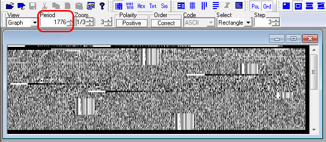
This burst-trasmision has been heard on 13505.0 KHz/USB at 1120 UTC (27 Oct). All of the burst waveforms use an 8-ary PSK serial tone modulation of an 1800 Hz carrier at 2400 symbols per second (fig. 1)

fig. 1
The analysis of the bursts say that they belong to the HF burst waveforms described in STANAG-4538 3G-HF, specifically: after the initial BW5 FLSU burst, there are four BW3 tansmissions which transport 4 x 512 bytes of data and two zero-filled BW3 transmissions which transpot 2 x 51 bytes of data. The transfer ends with a single BW4 burst. BW3 and BW4 waveforms are used by LDL protocol, as defined in STANAG-4538.

fig. 2 - BW3 burst
fig. 3 - BW4 burst
In a normal  LDL data transfer, the sending station and the receiving station alternate transmissions in the manner of figure 4: the sending station transmits LDL_DATA PDUs containing payload data  packets,  and  the  receiving  station  transmits  LDL_ACK  PDUs  each  containing  an acknowledgement  of  whether  or  not  the  data  packet  in  the  preceding  LDL_DATA  PDU  was received without error. The LDL_EOM PDU is transmitted using  the  BW4  waveform indicating that the entire user  datagram  has  been  delivered  to  the  receiving  station  without  errors ( LDL_EOM  PDUs  are  distinguished  from  LDL_ACK PDUs by context: any PDU sent using BW4 in the forward direction is an LDL_EOM PDU, while any PDU sent using BW4 in the reverse direction is an LDL_ACK PDU).
fig. 4 - 3G-HF LDL protocol transfer session
Conversely, in this recording there are no BW4 ACK bursts returned by the receiver station but only a final BW4 burst... unless the BW4 ACKs were transmitted and I did not receive them (Fig. 5):

fig. 5 - the heard 3G-HF session
The supposed lack of ACKs in figure 5 leads to think to a non-ARQ multicast transmission or a trasmission for recipients which are in EMCON (Emission Control): anyway STANAG-4538 does not provide the non-ARQ modality and the HDL/LDL protocols are for point-to-point applications only.

A possible scenario could be the use of the MDL-NACK protocol, Multicast Data Link with NAKs or MDLN. MDLN is a 3G multicast protocol with embedded retransmissions, it's added alongside the point-to-point 3G data link protocols HDL, HDL+ and LDL and shares many of the characteristics of the other 3G data link protocols (fig. 6).

fig. 6 - extended 3G-HF
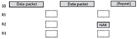
In MDLN each forward transmission is followed by a pause during which receivers that were not able to decode that transmission emit a very robust pseudonoise (PN) PSK symbol sequence to request retransmission (fig. 7). All receivers share the NAK slot. (Detection of the PN NAK sequence is sufficiently robust to allow any number of NAKs to overlap during the slot.) When the sender detects a NAK, it sends additional redundancy bits. Thus MDLN, like the point-to-point ARQ protocols, sends only enough redundancy to convey the message error-free. 
In our case, the data transfer is performed using MDL-512, a robust mode that uses a stream of 512-byte BW3 bursts. All recipients have decoded the entire transmission so we do not see NACKs.

fig. 7 - MDL-NACK opeation
MDL-MDLN protocol has been introduced in "Third Generation and Wideband HF Radio Communications" and in "Military Communications Conference, 2005" by E. Koski - Harris Corporation. The presence of the Citadel pattern (fig. 8) in the decoded bistream is a strong clue and would just confirm the use of Harris equipment. The transfer contains only one encrypted datagram. Obviously, the encryption is off-line.

fig. 8 - Citadel encryption