Showing posts with label Unids-PSK. Show all posts

8 April 2026

UNID Narrowband 2400 Bd High-Order Constellation Waveform

These signals were captured on 14430.0 kHz (USB) by my colleague ANgazu, who kindly shared them with me. Special thanks go to EA1FAQ for providing access to his SDR via the AirSpy Server Network.
The intercepted transmission consists of short time-synchronized bursts, occurring either as discrete pulses or in clusters of five. Occasionally, longer-duration bursts occur with no apparent correlation to the primary pulse train. These signals exhibit a bandwidth of approximately 3 kHz and a symbol rate of 2400 Baud. Spectral analysis indicates a high SNR. Figure 1 illustrates an example of this behavior (abridged-timeline view).

Fig. 1

Analysis of the Autocorrelation Function (ACF) exhibits strong peaks every 62.5 ms. At a 2400 Baud rate, this confirms a frame length of exactly 150 symbols (2400×0.0625=150). The structure likely consists of 122 unknown data symbols followed by 28 known probe symbols. This indicates that the signal is not a standard MIL-STD/STANAG waveform; based on available non-restricted documentation, none of the established standards utilize a 150-symbol framing structure.

Fig. 2: autocorrelation analysis

Figure 3 shows a rhomboidal (rotated) signaling constellation, as observed during the analysis of the longer bursts. This pattern strongly resembles High-Order QAM modulation. Notably, the symbols cluster toward the edges of the grid rather than forming a uniform "checkerboard" layout. This effect is likely attributable to Non-linear Distortion or Gain Compression (often termed AM-AM distortion). Such effects typically occur when a signal is recorded with excessive gain (clipping) or processed through an amplifier operating near its saturation point. Similarly, in a high-power transmitter, this occurs when the power amplifier is driven close to its physical limits to maximize efficiency, causing the outer constellation points to compress.


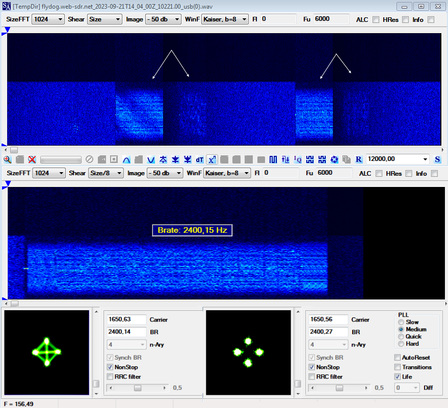
Fig. 3: rhomboidal (rotated) signalling constellation

In QAM, outer constellation points possess higher amplitudes; under saturation, these points are "compressed" inward or flattened against the boundaries, while inner points remain relatively unaffected. Furthermore, in the case of 64- or 256-QAM, the high symbol density means that without precise Symbol Timing Recovery, the constellation points converge into a blurred mass near the decision boundaries.
I analyzed one of the long bursts using an Octave script from my repository [1], and the result of Figure 4 closely approximates the constellation analysis shown in Figure 3.
 
Fig. 4
Then I used a different Octave script [2] to mitigate the effects of clipping and saturation and employing various decimation factors across several bursts. As demonstrated in Figure 5, this approach recovered the (suspected) QAM constellations, resulting in stable amplitudes, minimal IQ imbalance, and accurate frequency offset estimations.
 
Fig. 5


Subsequently, I specifically tested the signal from Figure 3 using a dedicated 256-QAM analysis script; the results are presented in Figure 6.
 
Fig. 6
According to these findings, the signal employs high-order QAM/APSK modulation.
The interpretation of 64/256-QAM is consistent with MS-110D Waveform IDs 10-12 and STANAG-4539, which support:

- 2400 baud in a 3 kHz bandwidth
- High-order QAM (64-QAM, 256-QAM)
- high spectral efficiency, with raw data rates of approximately 14.4 kbps (64-QAM) and 19.2 kbps (256-QAM), calculated at a symbol rate of 2400 baud with 6 and 8 bits/symbol respectively.

Although the constellation alone aligns with both MS-110D and STANAG 4539 standards, the observed 150-symbol periodic structure is inconsistent with the framing specified by either protocol (MS-110D 64/256-QAM modulations utilize 288- and 384-symbol frames, while STANAG 4539 employs a 287-symbol frame).
In HF environments, the Channel Coherence Time — the window during which the ionosphere remains quasi-stationary — typically ranges between 50 and 100 ms. The observed 62.5 ms probe interval offers significantly enhanced robustness compared to the MS-110D and STANAG 4539 standards (which feature durations of 120 ms, 160 ms, and 119.5 ms, respectively). By inserting a training sequence (probe) every 62.5 ms, the system enables the receiver to update its equalizer coefficients more frequently, allowing for more effective tracking of rapid channel variations and Doppler spreads that would otherwise degrade high-order QAM performance.

The analysis tends to confirm the detection of a highly optimized narrowband (3 kHz) waveform rather than a standard MS-110D or STANAG-4539 implementation. While it utilizes a single-carrier 2400 baud rate with high-order modulation, its unique 150-symbol periodic structure distinguishes it from established military protocols. This emission may represent experimental testing or a next-generation waveform currently restricted to non-public documentation or classified reference libraries. At the time of writing, I have no reports of further interceptions, at least not on 14430 kHz.


2 January 2024

unid PSK8 waveform

Unid PSK8 2400Bd serial waveform heard on 6987.0 KHz/USB, data transfers appear to occur in ARQ mode (Figure 1).

Fig. 1

The larger signal' segments have strong 66.66ms ACF spikes that make a 160-symbol framing consisting of 32 known symbols (mini-probe?) followed by 128 symbols of data. 

Fig. 2 - 66.66ms ACF and relative 160-symbol frame

The analysis of the frame' symbols (Figure 3) reveals that the mini-probes consist of a 16-symbol sequence which is repeated two times.

Fig. 3 - analysis of the frame symbols

Short segments too, maybe ACKs or some other negotiation messages, are PSK8 modulated and have a period of 768-bit/256-symbol length: at glance, it looks like a Walsh Orthogonal modulation mode (Figure 4).
 
Fig. 4


https://disk.yandex.com/d/fNYT-NOu7CPfbw

3 October 2023

QPSK 2400Bd unid waveform (Chinese modem?)

QPSK 2400Bd waveform heard on 10221.0 KHz USB around 1400 UTC, probably a Chinese modem.

Fig. 1

Autocorrelation of the signal produces sharp 16.6 ms spikes tnat makes 80 bit or 40 dibit symbols (QPSK modulation) period at the rate of 2400 symbols/sec. Indeed, after demodulation the resulting bitstream has a framing of 40 symbols length consisting of 20 known symbols (probe)

33031002310112003303

followed by 20 unknown symbols (data): obviously, since QPSK, 1 symbol = 2 bit. 

Fig. 2 - autocorrelation and bitstream

After the removal of the 20 known symbols, the initial & ending data blocks show 64-symbols/128-bit patterns even if - actually - the ending blocks consist of a 32-symbols/64-bit pattern (as it was already visibile in Figure 2).

Fig. 3

Fig. 4

 As usually, comments are welcome.

[1] https://disk.yandex.com/d/5g-pEgBTLIxSmg

18 July 2023

unid 100Bd PSK2

 Unid 100Bd PSK2 signal recorded on 4844.0 KHz and 6819.5 KHz USB (Figure 1)

Fig. 1

The demodulated bistreams, after differential decoding, show two different 133-bit length periods: supposedly, the first one (4844.0 KHz, Figure 2) is a combination of the source and destination address while the second one (6819.5 KHz, Figure 3) seems to refer to sending a message - several times repeated - to the correspondent. It's worth noting in the demodulated bitstream of Figure 2 what seem to be five "sections" following the header (that's the same in the two bitstreams).

Fig. 1


Fig. 2

More material is needed to fully understand the nature of such communications, comments are welcome.

https://disk.yandex.com/d/cDnTYrXiGDA1fA

29 June 2023

unid 2000Bd PSK8 burst transmission (720 symbols frames)

Unid burst transmission recorded on 5330.50 KHz/USB (60 mt HAM band) using a remote KiwiSDR locate at Oita, Japan [1]. The bursts have a duration of about 2606 ms with an interval of 3390 ms, the occupied bandwidth is 2200 Hz (Figure 1).

Fig. 1
 
The measured symbol rate is 2000 Bd on a 1274 Hz carrier: most likely 1200 Hz is the right value. The transitions diagram and the harmonic spectrum in Figure 2 show the use of PSK2 and PSK8 modulations, in particular PSK2 seems to be used for the initial preamble and for the inserts (miniprobes?) preceding the data blocks, the latter being modulated using PSK8. Obviously, PSK2 dibits are scrambled to appear on air as PSK8 tribit symbols.
 
Fig. 2 - PSK analysis
 
Bitstream analysis of a single burst, after the removal of the preamble, reveals the use of six frames (as indeed visible in the previous Figure 2) each characterized by a length of 2160 bits or 720 symbols. More precisely, each frame consists of a first sequence of 72 known symbols, followed by 72 unknown symbols (use of 720/72 symbols is curious) and finally by another 576 unknown symbols (216+216+1728 bit). Figure 3 clearly shows this frame structure. By the way, the initial 72 symbols sequence can be descrambled by the polynomial x^9+x^6+x^3+1 (1).
 
Fig. 3 - bitstream analysis

Symbols-oriented analysis of Figure 4 helps to better define the composition of the frames and particularly the used modulations. Indeed, looking at the 144 symbols diagram, the first 72 symbols are PSK8 modulated while the following 72 symbols are clearly modulated using PSK2.  Thus, each 720 symbols frame consists of an initial 72 known symbols sequence with PSK8 modulation, 72 unknown symbols with PSK2 modulation and 576 unknown symbols with PSK8 modulation.
 
Fig. 4 - symbols analysis

As from Figure 2, each burst has a duration of 2606 ms that - at the symbol rate of 2000 Bd - makes a total of 5212 symbols. Since each burst consists of six 720 symbols length frames, ie 4320 symbols, it follows that the initial preamble is composed of (5212 - 4320) = 892 symbols. Figure 5 shows the preamble and its symbols analysis, from which it can be seen that PSK2 modulation is used (except for some initial "uncertainties" due the SA generic PSK demodulator I used). Preamble can be descrambled using the polynomial x^6+x^3+1 (1).
 
Fig. 5 - preamble analysis

Evidence of Direction Finding (TDoA algorithm) indicate an area of the transmission site that could be compatible with Guam Island (Figure 6). However, in evaluating the goodness of such results it must be taken into account that the survey area is not densely populated with KiwiSDR receivers, especially in the East direction, and that the transmission was not continuous but - in fact - a train of bursts (although quite close together).

Fig. 6 - some Direction Finding (TDoA algo) results

https://disk.yandex.com/d/zu3AE6Ossjl_gQ 

(1) SA is a signal analyzer and not a decoder, therefore its phase-plane demodulator does not sync any particular sequence, as it happens for "suited" decoders, and phase-offset errors are possible. 

[1]  http://flydog.web-sdr.net/

10 November 2021

unid PSK8 2400Bd burst waveform

Unid PSK8 2400 Baud burst waveform spotted on 10557.0 KHz (CF) by using OZ1AEF KiwiSDR (Skanderborg, Denmark). ACF value is 293.4 ms, which makes a period length of 704 tribit symbols or 2112-bit length frames (figs 1,2). The resulting bitstream after demodulation does not have a well defined structure formed by known/unknown data blocks,  it could be a Walsh modulation but it is only a guess.

Fig. 1
Fig. 2

As a test I tried to analyze the bursts using a STANAG-4538 demodulator and surprisingly the decoder reacts but only to the first 700ms of each burst by identifying a 256 symbols initial segment (!) and a subsequent block of data (960 symbols only), even if not identifying any of the xDL traffic waveforms that it knows (BW1-BW7) and thus reporting the phase positions only:

6231017000770100000702070000001700000107010107000701070000000000
0000001001000070000010000000000107000000000000000010000000000000
0000000000000000000000000000000000000000000000000000000000070000
2357710003120162744325456425622470623725424155361132757073500120
 
0014030174251457266112142317764402235571057447051475133602436767
2703175471117746713161441063517300743117565244064305766450657067
3543135630554510775272301561043433561260120020160261523037545324
2056267511155732621360060321622731415212020343736426773247451624
1334736342650470251144547564221770112446074633674036402257132565
6167206436000663560205033075240623327644201057731763021170310231
2243202452744340766416127045073236601451345335341351405636207065
7530151204440026515461331365415522030410171723262531566213715260
5435401652143142551606034474235200464762472263162671465355421572
7246675441411506774573373574776501311646273035007266555622770517
4374175707126456760404241210370111043001250537550271063761077252
5455361471666153216322237212306173775100324261130557670052346734
3347363427504702511445475642217771124460746336740364022571325656
1672064360006635602050330752406233276442010577317630211703102312
2432024527443407664161270450732366014513453353423514056362070657

The period of the data bitstream is however in contrast to the value measured by the ACF (figure 3) but it could due to the short segment which is recognized and demodulated (700ms) and by now I still prefer to rely on SA.

Fig. 3

The shorter burts like those in figure 4 are instead recognized as BW0 waveform, Robust Link Setup RLSU protocol (1), although the latter has a slightly shorter duration, and then decoded:

11010000100010001010111011
11010100010010010000001110
11010000100010001010111011

Fig. 4

Regarding the initial segment of 256 symbols, mentioned above, it's important noting that the bursts of the BW0, BW1, BW4, and BW5 waveforms begin with 256 “throwaway” symbols that are sent while the transmitter level control and receiver AGC are settling (the so-called TLC/AGC guard sequence); this is probably the reason of the STANAG-4538 false-positives detections.

Despite this, I think that the similarity with the burst waveforms of STANAG-4538 should be taken into consideration in view for further insights and analysis of these signals.

https://disk.yandex.com/d/s8BveGOqLx_s2g
https://disk.yandex.com/d/X4z5LZJK59_QxA 

(1) robust burst waveform 0 (BW0) is used by the robust link setup (RLSU) protocol and carries a payload of 26 protocol bits

3 May 2021

unid, and somewhat peculiar, 1200Bd BPSK

Cleaning up one of my hard disks I came across an old recording (year 2014) that had no comment file associated with it, so I decided to take a look at it and see what exactly it was. The recording consists of different length bursts, each burst is modulated with PSK2 at a symbol rate of 1200Bd: nothing particularly interesting unless its ACF and, consequently, its period. Indeed, the ACF results in 373.74 ms (Figure 1) that make a length of the period of 448.5 bit (PSK2 @1200Bd), but after the differential decoding the bitstream shows a 897 bit length period, ie just the double of the value obtained using the phase detector. 

Fig. 1 - 373.74ms ACF corresponding to a 448.5 bit length period

As you know, a such situation is typical in asynchronous framings that have the stop-bit of 1.5 or 2.5 in length: for example, in case of a 5N1.5 framing the bit editor groups two 7.5 bit frames into a single 15 bit pattern because it can't represents a length of half bit. That's just what may happen here: the bit editor reshapes the bistream to a 897 bit length period and draws two frames (Figure 2) consisting of two 100 bit sync sequence, each followed by a data block.

Fig. 2 - 897 bit period

However, it's to notice in Figure 2 that the lengths of the two data blocks are different (348 and 349 bit) while the sync sequences have a constant length of 100 bit. Looking at Figure 3, the synchronization patterns are left and right inclined for periods of length 488 and 489 bits respectively: that behavior may confirm the 448.5 bit frame as measured above.

Fig. 3 - inclined 100 bit patterns in 448 and 449 bit framings

Talking about it with my friend cryptomaster, we agreed two possible hypothesis:

1) the length of the frame is 897 bit: the framing consists of  two 100 bit sync sequences that are interspersed with two data blocks of  348 and 349 bit; the variable length of the two data blocks and the two sync patterns are a proper feature of this waveform;

2) the length of the frame is 448.5 bit: the framing consists of 100.5 bit for the sync sequence (possible, even if unlikely) followed by 348 bit for the data block.

In order to verify the second assumption,  I set the speed of the PSK demodulator to a double value (2400Bd) so to emerge the missing half bit, if any. The resulting bitstream is shown in Figure 4: the period has the expected length of 1794 bit (2 × 897) and it's possible to see sync sequence patterns of 201 bit in length, ie just the extra bit that was missing.


Fig. 4 - 201 bit sequences in the bitstream @2400Bd

Indeed, the 1794 bit period is arranged as: | 201 bit sync  | 696 bit data | 201 bit sync | 696 bit data |;  since the speed of demodulation is doubled, dividing by 2 we get a 448.5 bit frame consisting of 100.5 bit for the sync sequence followed by 348 bit for data:
 

However, keep in mind that the above bitstream was achieved after a forcing of the demodulation speed to 2400Bd (instead of the effective 1200Bd) and the subsequent differential demodulation: more observations are needed to confirm the 100.5 bit length of the sync sequence.
By the way, the 100 bit sequence may be de-scrambled by the polynomial x^7+x^4+1. Looking for a scrambler polynomial in the 201-bit sequence does not make sense since the way it was obtained.
 
Fig. 5 - x^7+x^4+1 polynomial

Back to the signal, it's interesting to note that some burts have a ~230ms preamble consisting of 8 x PSK2 1200Bd "pulse" (Figure 6): I don't know the reasons and what it can depend on, signal strength and fading seem to indicate that it is not an exchange of messages between two nodes or an ARQ mode.

Fig. 6

 https://disk.yandex.com/d/SIqbhycJkrLjAg

5 March 2021

Rus PSK4 1200Bd

Transmission heard on 8741.5 KHz/USB, thanks to the KiwiSDR owned by YO3IBZ (Bucharest, Romania), on march 3rd. Although I tuned it on 8741.5 KHz I think the real tuning frequency be 8742.0 KHz (usual 1800 Hz subcarrier). As shown in Figure 1 the waveform employs a QPSK modulation at a rate of 1200Bd, ACF  result is 425 ms, ie 511 dibit symbols @1200Bd speed.

Fig. 1

As expected from ACF (511 symbols), the demodulated bitstream consists of a continuous repetition of the same 1022-bit pattern (Figure 2) thus - from time to time - I tuned it waiting for traffic, but luckless until it went off. All I can tell is that the signal was on-air all the "monitoring" period (ie 12 hours, from 0700 to 1900 utc), but in the following days and until today (March 5th), the transmissions seem to have ceased, at least on the reported frequency.

Fig. 2
 TDoA attempts clearly indicate an area south-east from Moscow as the most probable site of the Tx (Figure 3)

Fig 3

https://disk.yandex.com/d/O6yCdhU29f0Y3w

20 June 2019

unid QPSK 9KHz 4800Bd

Just working on the wideband signal spotted by Christoph first on 10160.0 KHz (cf) and more in detail discussed here in his blog. Replied his same results: period consisting of 984 bits (492 symbols) and 24-bit long sub-frames. As a further detail, I want just to add how the sub-frames seem to use different polarity.  Same result also for the geo location of Tx site (prob. Luxembourg).
Thanks to Christoph for reporting and sharing.


Signal recorded using the KiwiSDR owned by IW2NKE in Italy.

18 February 2019

unid signals from US KiwiSDRs
by ANgazu & Rapidbit

This signal was recorded tuning 5308 Khz and using some KiwiSDRs from the northeast of the US, mainly the one owened by K3FEF in Milford (PA). Since its various operating modes and its uncommon parameters, we decided to study it a little more thoroughly, leaving out the transmission purposes and the hypothetical users. The duty cycle of the signal is quite low so it took several hours of recording to collect signals suitable to be analyzed.

In the spectrogram of a recording we can see the bandwidth of the modes (Fig. 1). When several consecutive segments are transmitted, the separation between them is about 3m30s and the duration of the segments ranges between 94 and 106 seconds.

Fig. 1

mode 1
This mode has a spectral occupation of one 1000 Hz. The modulation is QPSK although with a notable majority of the symbols 0 and 2 and a speed of 600 Baud (Fig. 2). The ACF can be 840ms or 800ms and does not seem to transmit information, but seems  to be idling. After demodulation, bits aligned in frames of 1008 bits for ACF of 840 ms and 960 bits for ACF of 800 ms (Fig. 3).

Fig. 2
Fig. 3
 
mode 2
Its spectral occupation is about 1600 Hz. The modulation is QPSK with the same structure of mode 1, with a speed of 1200 Baud and an ACF of 420ms or 400ms. Also this mode exhbits a 1008 bits (960) frame with a very similar structure (Fig. 4).

Fig.4

mode 3
The modulation speed is 1200 Baud with a spectral occupancy of about 1400Hz. It is a GFSK with a shift of about 800 Hz andACF of 840ms or 800ms. The binary frame has a 1008 or 960 bits length (Fig. 5).

Fig.5
mode 4
The modulation speed is 300 Baud with a spectral occupancy of about 600 Hz. The modulation is an FSK with a shift of 400 Hz and an ACF of 3.35  or 3.2 seconds. Once demodulated, the frame is still 1008 bits or 960 bits just like the previous ones (Fig. 6).

Fig. 6


12 May 2018

unid PSK-8 bursts on 8040.0 & 11072.0 (all usb)

8040.0/usb 0755z 188-110A Serial, long sequence of 1200ms bursts (noise by adiacent Northwood HF-fax) bearing the same sequence


https://yadi.sk/d/WcrZVwFU3VkzfT 

11072.0 CF PSK-8 2800Bd, two stations exchanging 700ms bursts. The waveform fas a period of 140 symbols, most likely 40 symbols are used for mini-probes and 100 symbols for data. Bursts start and end with a short 2500Hz tone.


25 September 2017

5400 KHz (cf) 2380Bd mix-mode burst waveform
(by: i56578, ANgazu, KarapuZ, Rapidbit)


This is a very strange burst waveform modem that can be heard on 5398.2 KHz/USB (the central tone is exactly at 4000.0 Khz) at different times and SNRs. As Karapuz sais, probably it is Chinese equipment, but ANgazu guess the transmitter is near Spain, perhaps in Algeria: it's worth noting that there are 3 Chinese made ships in Algerian Navy and probably they maintained the factory radio-equiment:
http://www.defenceweb.co.za...Sea&Itemid=106 are
http://news.xinhuanet.com/english...29326.htm

The analysis of the bursts is not simple since the results exibith four different modulations in each burst (GFSK, MFSK-4, PSK-4, PSK-2), anyway all the transmissions have two fixed points (fig. 1):

-  constant manipulation rate of ~2380 symbols/sec 
-  all the bursts end with a PSK-2 segment

Fig. 1
Some good recordings can be download from here:
i56578-23-September
i56578-10-October 
Rapidbit-rec05

1. i56578-23-September recording
A detailed analysis of the bursts reveals a mix of GFSK 2380Bd/1500 and PSK-2 in both the two groups A and B, as shown in Figures 2-4.

Fig. 2 - group A
Fig. 3 - group B
Fig. 4 - modulation used

2. i56578-10-October & Rapidbit-rec05 recordings
The analysis of these recording reveals the use of QPSK and PSK-2 modulations in the group A and MFSK-4 and PSK-2 modulations in the group B (Figures 5-8).

Fig. 5 - group A
Fig. 6 - group B

Fig. 7 - QPSK and PSK-2 modulations used in group A

Fig. 8 - MFSK-4 and PSK-2 modulations used in  group B

3. observations & oddities
Tx windows are 4 min alternating short and long runs: the short transmissions are about 86 sec and the long ones last about 172 sec (twice the short). ANgazu recorded about 6 hours of monitoring period and processed the files using SA raster: as you can see, time window is 4 m. There are 13 transmissions and a no Tx period, building up groups of 14 frames starting by long Tx (Fig. 9)

Fig. 9

Each transmission consists of two groups of bursts (here termed "A" and "B"), possibly the group B is a repetition of A using different modulation to improve the reliability of the system. Every group starts using a longer carrier and a wider burst (about 2 sec). Unless some little variations, burts have a duration of ~720 msec and are spaced by a 500 msec unmodulated 1800Hz tone. It seems that if QPSK is used in the group A then group B will use MFSK; as seen, all the bursts end with BPSK segments.


In this signal, there are transients when changing modulation even if all modulations are BPSK, so no phase continuity is in use (Fig. 10)

Fig. 10

Phase vector rotates in one or other sense avoiding continous rotation in one sense. In this sample it can rotate both senses, mostly CCW or mostly CW (Fig. 11)

Fig. 11
In most systems, sync sequences are placed at signal start. In this one, after demodulated some BPSK bursts Sync seems to be 256 bits at the end (Fig. 12). Perhaps the burst shoul be reversed?

Fig. 12
(to be continued)