21 September 2020

48 KBaud OQPSK unid wideband transmissions


This post originates from an email from my friend KE9NS Darrin who noticed  a strange transmission around 6.8 MHz with an occupied bandwidth of about 48 KHz. According to his reports, the signal seems to start somewhere between 0000 and 0100 UTC, likely ON until sun rise. Interestingly, the signal tends to move around the band slightly probably trying to find an open slot in the band. Indeed, some breaks were observed and Darrin just noted that when it shut down for a break there was a STANAG 4285 signal within its 48 KHz passband: it must have realized and moved to an open spot.
Darrin kindly sent me his IQ recordings for analysys since it's impossible for me to get such samples using remote KiwiSDRs.

The waveform has a speed of 48000 Baud and occupies a band of about 48 KHz: as shown in Figure 1, the spectrum width, equal to the manipulation speed and the presence of the third line in the 4th power, lead to think to the Offset QPSK (OQPSK) modulation.

Fig. 1
Although GMSK and OQPSK have a lot in common, some further clues in favor of OQPSK come from the phase plane (Figs. 2a, 2b): OQPSK looks like GMSK with BT < 0.25 (the lower the BT index, the more it's similar to OQPSK).

Fig. 2a - OQPSK phase plane

Fig. 2b - syntesized OQPSK signal
 
Similar results were obtained from the analysis of CIS-1280 waveform (Figure 3).
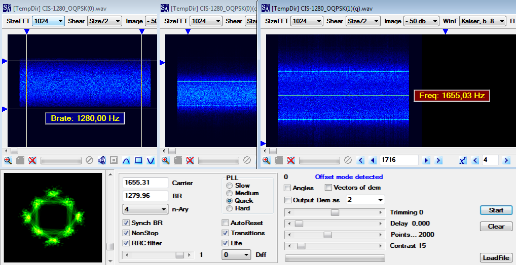
 
Fig. 3 - CIS-1280 OQPSK waveform

OQPSK is a constant-envelope modulation that has no 180-deg phase shifts and, therefore, has a much higher spectral containment than non-offset QPSK when transmitted over band-limited nonlinear channels. To further bandlimit an OQPSK signal, Shaped OQPSK (SOQPSK) was introduced and its initial version was referred to as MIL-STD SOQPSK after it was adopted as part of a military standard. 
 
Since OQPSK is like a GMSK with a small index, it is possible to do some demodulation attempts using the "FSK3 method" introduced by guys from radioscanner.ru [1]. In this regard, I also tried that FSK3 method by demodulating the 48 KBaud signal on three FSK levels (Figure 4) and then appropriately converting the ternary symbols through a small program written with Octave. It is difficult to establish the accuracy of the final bitstream, anyway the links to download the intermediate FSK3 file are below: everyone can try the demodulation by following the method described and post their comments and the obtained bitstreams.

Fig. 4 - FSK3 demodulation

Back to the 48 KBaud signal, it's always very strong, likely a very powerful transmitter. Quoting Darrin "Its a long shot but, the company that was supposedly trying to transmit stock trades via HF radio has a radio tower located in a town near to me. Supposedly they have a huge antenna array in Elburn, IL and transmit 20kw with an ERP of 808kw (very big stacked curtain log-periodic antennas) pointed 48deg and a special FCC license. It turns out, that antenna array is pointed directly towards my home in Bartlett, IL". We also thought of 188-110D App.D (per STANAG-5069) tests but such a waveform is not indicated.

https://yadi.sk/d/J76M1y-l-u42Sg (wav file) 
https://yadi.sk/d/_3o-UTVKEQpKNw (FSK3 demod)

[1] http://www.radioscanner.ru/forum/topic43183.html#msg865791

11 September 2020

110-220Bd/330 FSK, TMS-430/TC-535 (Swiss Army)

I56578, cryptomaster


This is the well-known Swiss Army 220Bd/330 FSK system consisting of the Telematik-Set 430 (TMS-430) [1] in combination with the cipher device TC-535 [2], the utilized HF transceiver is most likely the SE-430 [3]. This signal is commonly logged as "TMS-430", although TMS-430 is actually the DTE device, while the modem function is performed by TC-535 in conjunction wih SE-430.
These transmissions can be heard almost every day on 4495 KHz (CF) around 1800 UTC, a list of frequencies (apparently constant) at which this signal was noted is: 3502 4594 5182 and 5202 kHz; old logs also reports the 120Bd waveform. Recordings used in this analysis were made thanks to the Twente WebSDR and refer to the 4495 KHz channel. 
 
Looking carefully at the signal, it's possible to note short initial segments which are sent at the speed of 110Bd (Figure 1):
 
Fig. 1 - initial segment sent at 110Bd
 
This apparently oddity intrigued me and my friend cryptomaster and so we decided to study the demodulated streams in more detail. Since the TC-535 is directly connected to the HF transceiver, from the analysis of the stream it is possible to trace and verify the operating phases of the cipher. It's to be mentioned that, given the two speeds, the streams were obtained by demodulating the signal from time to time at 110 or 220 Baud depending on the bit segment that had to be studied; the demodulation speed used for a given figure is shown in its caption.
TC-535 Synchronization sequence (COMSEC preamble) consists of a PN (Pseudo Noise) sequence termed as "Synchronizing Template" sent at the speed of 220 Baud (Figure 2). In addition to synchronization, the PN sequence is also used for (encrypted) commands transmission.  Grouping the PN sequences into a single stream and analyzing it, turns out the presence of the polynomial x^7+x^3+1: likely this is just the 7-bit LFSR (indicated as C7 in the Control Unit circuit board) which generates the PN (pseudo noise) sequence.
 
Fig. 2 - the initial "sync template" sequence (demod speed: 220Bd)
 
The sync template is then followed by the  so-called "Additional Key" (AK): a time and key-dependent 64-bit block which is tree times repeated and sent in clear-text ASCII 8N2 at the speed of 110 Baud (Figure 3, in opposite polarity). The correct additional key information is obtained by majority decision from the three additional key blocks, which are identical under good transmission conditions, and mixed with the basic key to initialize the cipher generator at the receive TC-535 (thus the AK field may be termed as the Initialization Vector for TC-535).
 
Fig. 3 - the tree 64-bit Additional Key blocks (demod speed: 110Bd)

The sync phase (PN + AKs) is then followed by a 22-bit long alternating sequence of "0"s and "1"s  which separates AK blocks from encrypted data and allows the speed change to 220Bd (Figure 4).
 
Fig. 4 - 22-bit "01" sequence, also visible in Fig. 2, unless some bit in error (demod speed: 220Bd)

An optionally switchable FEC protection is built into the TC-535. If FEC is enabled, additional check bits are added to the data, which increase the data volume by a factor of 1.4 to 2.0 depending on the user code (Baudot/ASCII). In case of ASCII, the inserted check bits reduce the useful bit rate to half and consequently bit rate shall be increased by a factor of 2, thus the 220 Baud since the ASCII operational speed is 110 Baud. This clarifies the initial 110 Baud speed used to send the AK blocks (sent as async, clear-text, no FEC)! Note that the encrypted data are only transmitted in synchronous mode and returned asynchronously to the data sink.
The doubled data volume means that FEC encoder function is accomplished by a rate 1/2 convolutional coder (as indeed confirmed in [2], "Encryption method: Bitstream encryption"). Thus, the 220 Baud speed is a sign that FEC is activated and user data are ASCII coded. 
 
About the canche to trace a check matrix/polynomial in the streams, it should be noted that documentation says "The check bits are obtained from useful bits that have already been sent and added to the data to be sent before encryption", thus FEC encoding happens before the encryption process (!) and unfortunately there will be no interesting signs to look for in the streams. 
However, it can be noted that sometimes a single transmission carries more than one AK blocks (Figure 5), so we think that a single transmission may carry multiple messages/files, each preceded - most likely - by an appropriate an PN sequence.

Fig. 5 (demod speed: 220Bd)

TMS-430 (TelematikSet 430) consists of an NEMP-protected (protection against Nuclear ElectroMagnetic Pulses) device set in a large fiberglass box, consisting of: a notebook computer Toshiba 110CS, Pentium 100 MHz, VGA screen 11.3 inches, an Epson LX 300 matrix printer, two boot disks with DOS - based software.The (in the meantime no longer completely up-to-date) notebook is equipped with a hard drive, but is intended to be started from a boot floppy disk, if necessary any other commercially available IBM-compatible computer can be used. The messages to be transmitted can be recorded directly on the system, but usually a diskette is used to transfer the text message from the command post to the transmission office.
TC-535 (TeleCrypto 535) is more than "just" an encryption device since it also automatically controls the change of direction of the radio stations involved in the link. The most important features are the time and key-dependent initialization sequence, random filler text when in idle and the non-disruptive change of direction. The device is controlled via the TmS-430 keyboard.
As said, the utilized HF transceiver should be the SE-430. The complete communications system consists of a control unit (BE-430), usually connected to a encrypter, and a radioteletype machine. The signal is transferred over field telephone lines to the transmitter site, which can be installed at quite a long distance. The transmitter site equipment consists of the transmitter SE-430, it's power supply SG-430 and the automated antenna tuner AG-510/430.

Fig. 6 - TMS-430 (on the left) and TC-535 (source: Historisches Armeematerial Führungsunterstützung HAMFU)

https://yadi.sk/d/8xDdmoSlMhEJig
 

28 August 2020

CIS Navy VLF 50Bd/75 FSK (T-600 75Hz)

50Bd/75 FSK is the T600 waveform variant utilized by Russian Navy on 18.1 kHz, commonly for submarine communications.

Fig. 1 - 50Bd/75 waveform
 
As seen in CIS 36-50, frames are constructed from data blocks consisting of 7-bit words with a fixed ratio of '1's vs. '0's of 4 to 3 or vice versa, depending on polarity of reception (Figure 2). 

Fig. 2 - 4/3 ratio test on a five-message transmission (s1 and s2 data blocks are the same)
 
Multiple Russian military naval communication stations share this frequency (18.10 KHz) and the call sign "RDL".  The 24h transmission schedule has frequent flash-override messages in A1A Morse, FSK-Morse and T600 75 Hz, as shown in the lower image of Figure 1.

https://yadi.sk/d/0M7f_H_WOD9LTA (T600-75 bitstream)

22 August 2020

Swedish Navy submarine MSK multi-channel broadcast


(For background it might be helpful to read the relevant entries here)

Swedish Royal Navy (Swedish: Svenska marinen [1]) uses a broadcast function of STANAG-5030 (1) for communication with its subs in the Baltic Sea, the return channel is believed to be low-end HF. These LF broadcasts use the 200Bd/100 MSK waveform and can be heard on 40.4, 42.5, and 44.2 KHz (CF) by using  KiwiSDR receivers located in the island of Gotland which have a good SNR. [2].

All the three signals have the classic set of parameters for (G)MSK: a spectrum equal to 1.5*Br (300Hz), shift equal to Br/2 (100Hz), a characteristic bell-shaped appearance (Figure 1), and others such as 4-point constellation, transitions and real trajectories (Figure 2). Please note that the carrier in the fourth degree is very weakly expressed, sometimes it is practically invisible at all.

Fig. 1
Fig. 2
Using 200Bd MSK (a form of QPSK) it is possible to transmit two 100 Baud channels X and Y, each on a pair of phase, and each channel can consists of 2x50 Baud multiplexed channels. Thus, MSK can provide a TDM multi-channel broadcast of  up to 4x50 Baud X1 X2 Y1 Y2 channels within the 200Hz assigned band (MSK4).  Some aspects about the similarities bewteen QPSK and MSK are covered in radioscanner forum [3].

In conditions where no messages are available for transmission, the four channels are arranegd with two "empty channel filler" (ECF) patterns, probably generated automatically at the transmitter equipment:
- two channels share the same 15-bit pattern;
- a third channel uses a different 5-bit pattern;
- the fourth channel uses the same 5-bit pattern where one column is repalced by the bits of the pseuso-random sequence generated by the polynomial x^31+x^3+1.
An example of this "idle" mode is shown in Figure 4: here the m-sequence is sent in the Y2 channel (notice the same pattern sent in X1 X2 channels ).

Fig. 3
A more generalized scheme highlighting the position of the m-sequence channel in four different recordings is shown in Figure 4.

Fig. 4
 In case of messages, the four channels use a 5-bit format with different framings:  
- two channels share the same 5-bit framing, i.e 1-bit marker (pos/neg according the polarity) + 4-bit data:
- a third channel uses an unid (to me) framing;
- the fourth channel uses the same 5-bit framing of the first two channels but the marker column is replaced by the bits of the pseuso-random sequence generated by the polynomial x^31+x^3+1.
Figures 5a,5b show such arrangement.

Fig. 5a
Fig. 5b
Due to their strategic and tactical importance, subcomms require secure cryptographic protocols and this could explain the presence of the x^31+x^3+1 pseudo-ramdom sequence which is used to sync the receive KW-46/KIV-7 ciphers (other than to permit channel identification), although an encrypted 4-bit stream is rather unusual as well as the use of the 1+4 bits frames. 
In this regard, one might even think that the actual secured messages channel is Y before the TDM split (Figure 6), while the other channels X1 X2 transport not critical 4-bit coded data (WX forecast, sea conditions, ...). This way, messages could use 10-bit START-STOP code which is then encrypted using the KW-46/KIV-7 equipment. Encryption results in bits 2 to 10 being encrypted and bit 1 (START) being replaced with unencrypted bit defined by the polynomial x^31+x^3+1, or in reverse order - bits 1 to 9 encrypted and bit 10 (STOP) replaced (2). A second hypothesis - perhaps the most likely - is that each channel is encrypted with a specific cipher ...but these are just my speculations.

Fig. 6 (m-sequence columns are highlighted)

The results of TD0A geolocation indicate three probable transmitter sites that match fairly exactly with those indicated in a map presented by FMV (the Swedish Defence Materiel Administration) [4] at the March 2020 HFIA HF Industry Association [5] Meeting in San Diego, CA (Figure 7):
- 40.4 KHz: SAS/SRC Varberg
- 42.5 KHz: SAS2 Gudinge
- 44.2 KHz: SHR Ruda

Fig. 7

It must be taken into account that I can't record the (KiwiSDR) LF spectrum 24/7 so the results indicated above may be incomplete: further recordings are needed and possibly an update post will be published later. Hints and comments are welcome.


(1) STANAG-5030 is a restricted document so no information is publicy available. Moreover, the new STANAG-4724 "VLF/LF MSK Multi Channel Broadcast" is currently being ratified by NATO member states as next evolution:

(2) max success for x^31+x^3+1 in Y stream was found for a length frame of 10 bit; that same frame does not have parity bits (x^31+x^3+1 column excluded from the checksum)


4 August 2020

(yet another) 100Bd/500 FSK-2


4 August 2020 update
some frequency, same timing, and same 511-bit sequence but the speed has switched to 50Bd (shift remains unchanged, 500Hz):


It's to notice that the 511-bit sequence is obtained using the seed  s=[0 0 0 0 0 0 0 0 1]  and transmitting the output in opposite polarity (i.e., inverting the polarity of the demodulated sequence we get the exact sequence generated with seed s=[0 0 0 0 0 0 0 0 1]):

up: LFSR sequence when seed = [0 0 0 0 0 0 0 0 1], down: received sequence after reversing the polarity

2 August 2020
Just to log interesting 100Bd/500 FSK-2 transmissions found on 9130 KHz (CF). Data sent consist of a repeated 511-bit pseudo-random sequence which is generated by the polynomial x^9+x^5+1 (Fig. 1); likely that sequence is used when no data to transmit is available or to mantain sync between transmitting and receive modem (see also ITU Recommendation O.153 [1]). Since the 100Bd/500Hz waveform is used in several systems, it's difficult to state the source; anyway, it's to notice that x^9+x^5+1 sequences (PRBS9) are also used in CIS-12 and more generally in T-230 family devices.

Fig. 1 - the 511-bit pseudo-random sequence

Looking at the two FSK tones, it seems that they preserve their phase after each switch-over (Fig. 2). By the way: F1 = 753.87 Hz (1:0.001326479), F2 = 1253.68 Hz (2:0.001595299), dF = 499.81 Hz.

Fig. 2

I followed the transmissions for some days, they usually take place on weekdays at 0943 and stop at 1100 (UTC times). I ran several TDoA attempts and results point to the Moscow area, unfortunately they do not exactly agree.

Fig. 3 - start stop period

Fig. 4 - some of the TDoA results