The analysis concerns short transmissions monitored on 3824.0 KHz/USB within the 80mt Ham Band (1) thanks to SM1OTX Airspy HF+ in Sweden and OZ1AEF KiwiSDR in Denmark. According to my observations, at least on this channel (3824 KHz/USB), daytime transmissions occur at intervals of 15 minutes but not with a fixed schedule (for sample: hh05, hh20, hh35, hh50; hh10, hh25, hh40, hh55; hh08, hh23, hh38, hh53) and if there are messages to be sent. The transmissions seem less frequent at night, but I don't have enough IQ monitoring to say for sure; however I have noticed that - at night - the same frequency is sometimes occupied by CIS-12 transmissions.
I ran several Direction Finding tests using the TdoA algorithm and all the results point to an area south from Stockholm, probably the NAVCOMMCEN of the Sweden Defence (Figure 1).
 |
Fig. 1 - Direction Finding results
|
In this regard, it's worth noting the use of the 3824 KHz frequency. Indeed , at that high latitudes, due to the long dark periods and the sun low on the horizon during winter, the low portion of HF must be used (lack of F layers). The 80 meter band is certainly the best choice for medium distance contacts (eg ships in Baltic Sea or Gulf of Bothnia) as it guarantees 100% reliability over 24 hours (Figure 2) and is suitable for NVIS (Near Vertical Incidence Skywave) mode propagation for local contacts.
 |
Fig. 2 - Circuit Reliability for 80 mt comms between medium distances
|
Below the results of my analysis, aimed to understand and write down the Protocol Data Units (PDUs) of the datalink protocol and the way their fields are encoded. Please notice that the "designations" used are only mine and are introduced just for convenient reference.
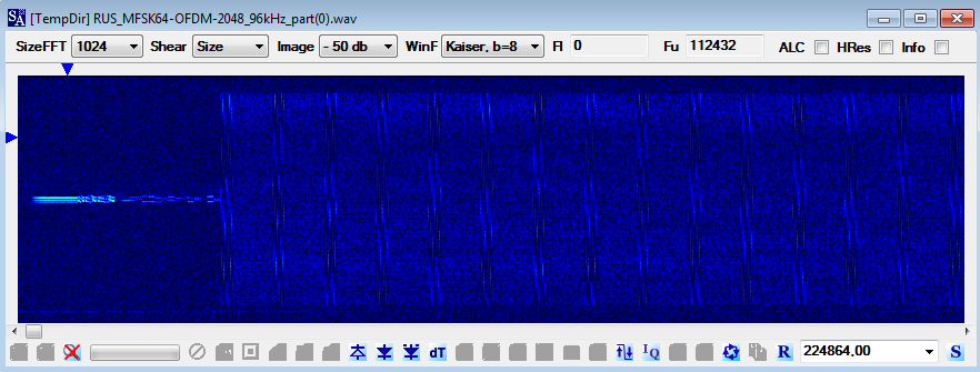
The MIL-STD 110A (MS-110A) 1200bps Short Interleaver is the used HF waveform (Figure 3).
 |
Fig. 3 - MS-110A waveform and ACF (66.6 ms)
|
Sometimes it may happens to see fast exchanges (bursts 1-4) before a "usual" data transfer: judging by the fading patterns in Figure 4, two nodes are involved.
 |
| Fig. 4 - fast exchanges before a data transfer |
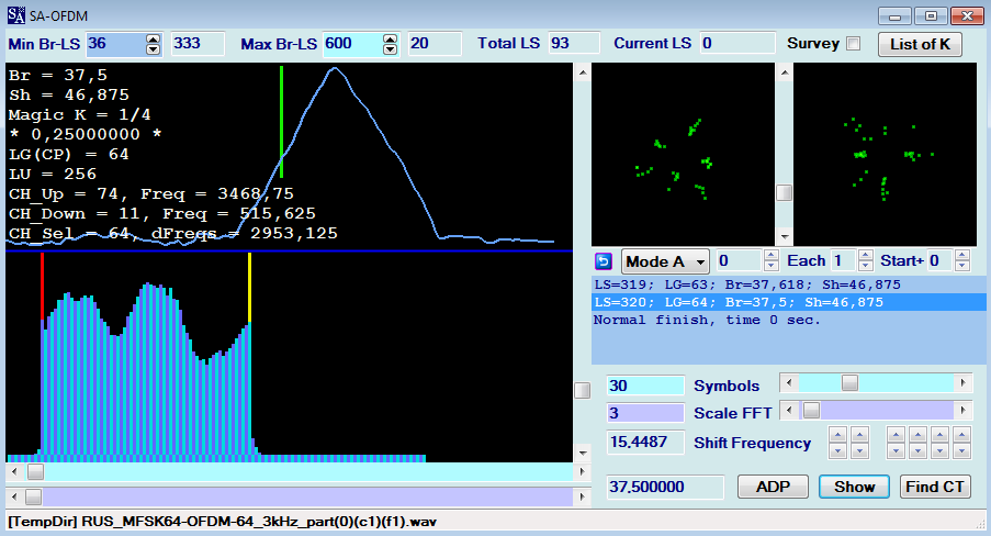
Discarding the MS-110A waveform overhead, the bitstreams exhibit a 104-bit period: data blocks, well-defined structures and repeated patterns are clearly visible in Figure 5.
 |
Fig. 5 - a bitstream after the removal of MS-110A waveform
|
|
Blocks are delimited by long series of logical "1s" and are composed of up to 17 datagrams. Each datagram starts with a synchronization-type PDU (S_PDU) followed by data-type PDUs (D_PDU):
 |
Fig. 6 - general structure of a MS-110A transmission
|
synchronization-type PDU (S_PDU)
The S_PDU consists of a common 40-bit/5-byte sync sequence
(2)[0111111001111110100010111001100010111001] 0x7E7E8B98B9
followed by a 104-bit/13-byte chunk of data which is repeated three times. After synchronizing the bitstreams on the sync sequence and a length of 144 bits (ie: sync + ACF), the 13-byte chunk is formed of (Figures 7,8):
- a specific 8-bit field
h (designated a
header)
- a 40-bit/5-byte field
m - a common (!) 32-bit/4-byte sequence
s[11101010011010100010001001100010] 0xEA6A2262
- a 3 bits ("000") string
- a 21 bits field
n
 |
Fig. 7 - a synched bitstream (first 144 bits)
|
 |
Fig. 8 - bit-field map of the synchronization-type PDU (S_PDU)
|
data-type PDU (D_PDU)
The D_PDU consists of 80-bit/10-byte field p (designated a payload) followed by a 3 bits "000" string and a final 21 bits field q (Figures 9,10): notice that the final part is the same as the one of the S_PDU.
 |
Fig. 9 - datagrams consisting of a S_PDU followed by D_PDUs
|
 |
| Fig. 10 - bit-field map of the data-type PDU (D_PDU) |
The general structure of a datagram is shown in Figure 11:
 |
Fig. 11
|
I spent some days studying the bitstreams and trying to understand the meaning of the fields of both S_PDU and D_PDU, and I came to the following conclusions.
Header field
The argument of the 8-bit header field of the S_PDU is coded as described in CCITT V.42 paragraph 8.1.2.2, which specifies that the least significant bit of a 1-byte argument shall be transmitted first. Therefore, after its conversion into a decimal number xyz, I found that the field it indicates the number of the useful bytes of the datagram and the eventual presence of a filler in the last D_PDU of the datagram.
Given that:
- each D_PDU has a payload of 10 bytes (40 bits)
- the header field of the S_PDU is a 8-bit field
the system is designed so that each datagram may contain up to 255 bytes of data (11111111). For example (see Figure 12):
xyz = 130: 130 useful bytes, 13 complete D_PDUs, no padding
xyz = 126: 126 useful bytes, 12 complete D_PDUs + 6 useful bytes in the 13th D_PDU (the remaining space is filled with four 0 value bytes)
xyz = 118: 118 useful bytes, 11 complete D_PDUs + 8 useful bytes in the 12th D_PDU (the remaining space is filled with two 0 value bytes)
So, the max value of the header field (255) stands for: 255 useful bytes, 25 complete D_PDUs + 5 useful bytes in the 26th D_PDU (the remaining space is filled with five 0 value bytes).
 |
| Fig. 12 - meaning of the header field of S_PDU |
That meaning of the header field is also confirmed by analyzing the bistreams of the bursts in Figure 4
- burst 1 (header: 01101110) carries 110 bytes of data within a single datagram of 11 D_PDUs
- bursts 2,3,4 (header: 00001110) carry short 14-byte "messages" in 2 D_PDUs and six padding bytes
 |
Fig. 13
|
(It is practically impossible to define the nature of these short 14-byte
messages, one can only assume that it involves some form of negotiation
between the two nodes. Likewise, it cannot
be said whether these messages are due to the operator intervention or
whether they are automatically generated by the protocol, as is the case
with STANAG-5066)
FEC
The argument of field q of the D_PDU consists of the 21-bit Cyclic Redundancy Check (CRC) applied and computed on the first 83 bits (ie payload p + "000"). The same consideration can be made up regarding the S_PDU, where the argument of field n is the 21-bit CRC field and fields h+m+s + "000" form the 83 bits which shall be coded.
Indeed, thanks to the help of my friend cryptomaster, we found a (104,21) matrix generated by the polynomial:
x^21+x^18+x^17+x^15+x^14+x^12+x^11+x^8+x^7+x^6+x^5+x+1
which is well suited to the specific case.
 |
Fig. 14 - (104,21) matrix used for CRC
|
I coded a short Octave script and tested the check sub-matrix on the first 83 bits of both the types of PDUs, results are shown in Figures 15,16: the check-matrix works like a charm! So, if we consider that fields are structured in bytes, the 000 bits act as kind of padding added to the word being coded and a (104,83) FEC coding is used (BCH? LDPC?).
 |
Fig. 15 - check matrix applied to the S_PDUs
|
 |
| Fig. 16- check matrix applied to the D_PDUs |
Encryption
In this regard I extracted and merge together more than 500 D_PDU payloads into a single stream then I performed some tests on it. The quality of the cryptography can be evaluated with a statistical method or by calculating the Shannon Entropy (3) and the Index of Coincidence (IC) (4) of the stream.
The statistical test (Figure 17) determines the randomness, the number of single bits in the stream is counted, then the double bits, then the triple bits and so on to the end. The result is a graph: if the information is not systematic, the adjacent columns should be half the size of the previous ones. The test shows good encryption quality.
 |
Fig. 17
|
The measure of the Shannon Entropy can be used, in a broad sense, to detect whether data is likely to be structured or unstructured. 8 is the maximum, representing highly unstructured, 'random' data. Properly encrypted or compressed data should have an entropy of over 7.5 while a low IC generally means that the text is random, compressed or encrypted (Figure 18):
Shannon entropy: 7.948409571238646
Index of Coincidence: 0.039349499261437125
 |
Fig. 18 - Shannon Entropy and Index of Coincidence
|
If my guess is correct, the string m of the S_PDU is an Initialization Vector (repeated 3 times) of a stream cipher and thus the preamble is actually a COMSEC preamble consisting of bit sync, header, Initialization Vector, frame sync and a final CRC field.
A Secure Text system?
According my analysis, the PDUs of the used datalink protocol consists of the following formats (please notice that the 3-bit field encoded with the value "0" could be specified as NOT USED):
 |
| Fig. 19 |
|
But what kind of comms we are speaking about?
- although a datagram may contain up to 255 bytes of data, according my recordings each datagram is composed of no more than 130 bytes of data: such brevity could mean that the datagrams are made up of short text messages;
- transmissions occur almost regularly every 15 minutes, as if the sender station collects messages coming from one link and then group and forward them into another link;
- transmissions are in a "blind" way, i.e. they are not preceded by 2G/3G ALE neither by voice calls and are not followed by ACKs: this could mean transmissions addressed to "stared" receiver(s);
the above issues make me think of a Secure Text system, ie a system that allows text and data exchange up to and including the level of secret and protected by cryptographic devices (5).
A good point in favor of my guess is that Swedish Armed Forces currently use a variety of national secure text messages that are not interoperable with international systems and are distributed just through the MaRA Naval Communications Centre (NAVCOMMCEN) for maritime platforms and operations [1].
...some speculations
Since Sweden Defence use national crypto for domestic comms (6), what about the MGZI "Kryptomodem 1401" (Kryapp 1401, Crypto Modem for serial communication) commissioned by FMV (Swedish Defense) to Sectra [2]?
 |
Fig. 20
|
The Swedish Defence Materiel Administration (Swedish: Försvarets materielverk, FMV)[3] is a Swedish government agency that reports to the Ministry of Defence. The agency is responsible for the supply of materiel to the Swedish defence organisation. In this case they also provide Kryptomodem 1401 to the Swedish Navy. Notice in Figure 21 that maybe the "Stri 8000" could be identified with the HF-8000 SDR Radio System prioduced by ELBIT (ELBIT Sweden is one of the supplier of Swedish Defence).
 |
Fig. 21
|
https://disk.yandex.com/d/3qW7_b3IbdkEGw
(1) The 80-meter or 3.5 MHz band is a band of radio frequencies allocated for amateur radio use, from 3.5 to 4.0 MHz in IARU Region 2, and generally 3.5 to 3.8 or 3.9 MHz in Regions 1 and 3 respectively. European common allocation is AERONAUTICAL MOBILE (OR) FIXED LAND MOBILE
(2) It must be said that in many messages the sync sequence seems to be 48 bits starting with [00000000] 0x00
(3) In the context of information theory, Shannon's entropy is a measure of the rate at which information is produced by a source of data. It can be used, in a broad sense, to detect whether data is likely to be structured or unstructured. 8 is the maximum, representing highly unstructured, 'random' data. English language text usually falls somewhere between 3.5 and 5. Properly encrypted or compressed data should have an entropy of over 7.5
(4) 0 represents complete randomness (all characters are unique), whereas 1 represents no randomness (all characters are identical). English text generally has an IC of between 0.67 to 0.78 whereas 'Random' text is determined by the probability that each letter occurs the same number of times as another. A low IC generally means that the text is random, compressed or encrypted.
(5) Secure text systems enable the armed forces to transmission and receipt military request, reports, orders, plans and policies and can be achieved in different ways, both regarding the format of the message and its method of transmission.
(6) A few words on Swedish cryptology
For two centuries Sweden has upheld neutrality in the sense that the country has not been member of any military alliance. Only recently did the country apply for NATO membership although it has been a public secret that Sweden since the end of WWII has had an informal, but quite strong collaboration with NATO countries, especially the Scandinavian countries including Finland with which strong historical, cultural and linguistic bonds exist. The cooperation has manifested itself in the area of signals intelligence, exchange of intercepted information and interoperability of communications equipment including crypto equipment, and more recently in a close collaboration with NSA.
The credibility of neutrality has been supported by strong defense forces, including cryptologic efforts. A few cases serves to lustrate this: In spite of its neutrality, Sweden was able to just a short time after Germany attacked Denmark and Norway in April 1940 by systematic interception to reading German military telegraph traffic, which transited Sweden, by cracking the so called Geheimschreiber (a kind of substitution cipher where the key was changing with each character and the initialization vector was altered with a few days’ interval) primarily based on the attack by a mathematical genius, Arne Beurling.
Another feat was the successful evacuation – operation Stella Polaris - of the entire (nearly) Finnish SIGINT staff, their families and crypto analytic material and equipment after the Russo-Finnish war in 1944 ended in Finnish defeat.
Already in 1942, all cryptological and cryptanalytic effort were concentrated in FRA, Försvarets Radioanstalt (Defense Radio Establishment).
Thus, for many years the crypto efforts of Sweden's defence forces and government communications have had a high priority as a national endeavour, mainly due to the centuries long Swedish neutrality, as described above. Today, as Swedish membership of NATO is imminent pending ratification by the Turkish parlament, this collaboration of long duree ensures that the transition from neutrality to NATO mebership will be smooth. There is no doubt that the navy of Sweden in the actual geopolitical situation will play an important regional role in the Baltic Sea and the approaches to this ocean area.
The designations of Swedish crypto equipment is quite straightforward:
MXY[Z] - Maskinkrypto; Machinegenerated crypto
X - G = Gemensamt (common for all service branches), M - Marinen (navy), L - Flygvapnet (air force)
Y - Typ Y; Type Y
[Z] - Optional designator; Z = I, for international use, Z = U, for use abroad
The equipment is graded according to its degree of signal protection (Sw., SG, signalskyddsgrad), i.e. SG R(estricted), C(onfidential), S(secret) and T(op) S(ecret).
[1] https://docplayer.net/45022367...internet.html
[2] https://communications.sectra.com/case/encryption-solutions-for-the-swedish-defence/
[3] https://www.fmv.se/english/