Showing posts with label Initialization Vectors. Show all posts

4 December 2024

256-bit IVs & 0xD1E221E1 sequence

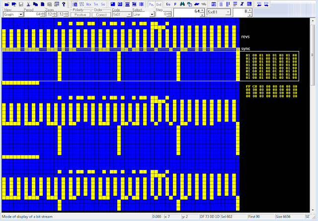
Just a quick note to observe that bitstreams using (alleged) 256-bit Initialization Vectors (IV) encryption have the same 32-bit/4-byte sequence repeated three times. For example, in the bitstream in Figure 1 (MS-110A transmission) you can clearly see the 256-bit IV sequences, each repeated eight times. 

Fig. 1

But if you reshape the same bitstream into columns of 32 bits the same 32-bit sequence 0xD1E221E1 emerges (Figure 2).

Fig. 2

I have previously encountered bitstreams with 256-bit IVs [1] but at that time I had not investigated further, focusing only on those sequences. As a counter-proof, I took back and analyzed those signals and - surprise - they also all present the same sequence 0xD1E221E1 after the IVs (Figure 3).

Fig. 3

It should also be said that I have also encountered the sequence 0xD1E221E1 three times previously [2] but, when I re-analyzed those transmissions, the 256-bit IVs were not found (Figure 4).
 
Fig. 4

Both for the position of the 4-byte string 0xD1E221E1 (after or WITHOUT the alleged IVs) and for its presence in different streams it is difficult to say whether it identifies a sync string for a cipher device or whether it identifies a particular datalink protocol. However, in all cases I could analyze, STANAG-4538 (3G-HF) "circuit mode service" is used along with MS-110A as the traffic waveform.
Comments and suggestions on this matter are welcome!
 

[1] https://i56578-swl.blogspot.com/2020/09/s-4538110a-transmissions-using-unid-256.html
[2] http://i56578-swl.blogspot.com/search/label/P%3D32

30 March 2023

S-4538/110A transfers using 256-bit Initialization Vectors (2)

Recently I analyzed an interesting recording sent me by my friend Mike (mco) some days ago; for clarity, the transmission was recorded on 8006 KHz/USB. As shown in Figure 1, the recording consists of four data segment sent using the 188-110A Serial Tone (at 600bps/S), two 188-141B async call PDUs ("obsoleted", 3G-ALE)(1) and a final FLSU (Fast Link SetUp) PDU that terminates the link, the latter BW5 waveform suggests a STANAG-4538 3G-HF "circuit mode service" transmission, as well as the use of the 141B async call suggests the use of Harris equipments.

Fig. 1

The bitstream after 110A removal (Figure 2) clearly shows the use of encrypted frames which are characterized by the use of 256-bit length Initialization Vectors (IVs), thus the data-link protocol is also encrypted (not the data only). It's to be noticed that each Initialization Vector is 8 times repeated.
 
Fig. 2

The frame structure appears almost the same of the one analyzed in a similar transmission analyzed some times ago [1], in that case the 110A modem was used at 2400 bps/S. Studying more closely the four bitstreams, it's possible to see recurrence of a same COMSEC preamble consisting of 01s sequences for bit phasing, same repeated sequences (probably for frame sync), and obviously the four different 256-bit length Initialization Vectors (Figure 3).
 
Fig. 3

phasing

223-bit sequence sync:
0101101111011010010000100011110110111101110000100100001111000100010111011010001110100101101110111
1011100001001000011110001000101110000100011101001011011101111011100001001000011110001011010001001
00001110111101101000100011110

256-bit Initialization Vectors, each 8 times repeated:
E7 F6 45 FD 63 53 2A 4B 91 0B 0E B7 A8 80 00 00 
63 35 D7 73 64 9B 8D 08 35 3F 26 0D 9D BE 02 F9 

D7 32 3B 83 D0 6F 57 03 A9 65 CA F7 64 64 00 00
9B 32 8E B9 2B D0 9D D6 00 FB 96 53 68 92 BD F5 

87 32 AA F0 9C 3D 03 EE E2 00 26 EF 45 4D 00 00 
82 8F C3 CC BF 2B 36 99 51 27 45 88 9D 83 2E F7 

77 CD 93 E5 EB AF 65 3D B6 2B 1A 47 4E 19 00 00
C6 E1 5C FA 8B 16 57 57 0E 2B 04 C9 65 66 25 F3

phasing

32-bit sequence sync (6 times repeated):
8B 87 84 7B

The COMSEC preamble is followed by encryption, according to the standard MIL 188-220D [2].

Fig. 4
 
For what concerns the encryption, I would speculate the use of "HC-256", a software stream cipher for embedded systems which generates keystream from a 256-bit secret key and a 256-bit Initialization Vector [3], but it's just a guess.

 
(1) 188-141B (released on March 1999!) was superseded by 188-141C (December 2011), in its turn superseded by 188-141D (December 2017): the last two standards no longer have the Appendix C but only some short paragraphs, among them the #C.6 says "The specifications previously contained in this appendix have been replaced with reference to the essentially identical NATO STANAG 4538". 

[1] https://i56578-swl.blogspot.com/2020/09/s-4538110a-transmissions-using-unid-256.html
[2] http://everyspec.com/MIL-STD/MIL-STD-0100-0299/MIL-STD-188-220D_CHG_NOTICE-1_24817/ 
[3] https://www.ecrypt.eu.org/stream/ciphers/hc256/hc256.pdf 

3 February 2022

a curious STANAG-4285 transmission

Really curious STANAG-4285 transmission sent me by my friend IK1YDE Andrea who was the first to spot and analyze the signal. The oddity is that, after S4285 demodulation, the Initialization Vectors, as well as being repeated within each message, consist of the unique(!) and a bit "basic" sequence: 0x0001000100010001 (see figure below).
Actually, KG-84/KIV-7 devices use 2 x 128-bit sequences as IV and these sequences - as well as in other crypto devices - change with each new message, even if the same message is repeated (in this case 0xFFC00000000000000000000000000000).  

Fig. 1
 
Andrea heard that transmissions on 4165.6 KHz/USB, the only (Freq/Mode) match I found dates back to 2005 and refers to French-Ny FUE. No other interception in recent days, even if sporadically monitored.  No idea what this transmission is, maybe tests of new setup?

3 November 2021

again about crypto devices with (5x) 128-bit Initialization Vectors

Recently in the list of the UDXF group a log of the UTE listener howardhawks (HH) appeared about transmissions of the Royal Navy of Oman (RNO) in 110A 1200bps/S mode on 8403.0 KHz/USB: nothing special except the use of encryption with 128-bit length initialization vectors, as indicated by KarapuZ in his comments to the message. This fact intrigued me and, since I have already met crypto systems that use initialization vectors of equal length and with the same format (ie five times repeated) [1], I decided to monitor those transmissions and collect some recordings to compare with other similar ones stored in my hard disks, ie:

- STANAG-4285 from Croatia (TDoA), recorded on January 2020 (*)
- 110A and STANAG-4539 attribute to the Swiss Emergency Network, recorded on October 2017 (*)

The bitstreams after demodulation of the above signals are shown all together in Figure 1:

Fig. 1 - COMSEC preambles using 5x128-bit length IVs

As you can see, the three COMSEC preambles - highlighted in figure 1 - have the same pattern, regardless of polarity:

  • 000110000100000111000101111001011011101101001001011111010101 60-bit length frame sync
  • 128-bit (16 bytes) sized Initialization Vector (5x)
  • 0101010101010101010101010101010101010101010101010101010101010101 64-bit length phasing/idling sequence

I don't know if it's an external COMSEC devices (ie standalone equipment such as KG-84) or communications equipment with built-in COMSEC, the fact is that the preambles are the same and this leads me to think that the above  transmissions - coming from three different countries/organizations - are secured by the same COMSEC device. In this respect, it would be important to know which providers of communication equipments the above users have in common.

By the way, signals gathering has been possible thanks to the KiwiSDRs operated by Kuwait Amateur Radio Society [2]. Transmissions on 8403.0 KHz, at least those listened to, mainly consist of voice calls/radio-checks and short exchanges of  messages using as mentioned 188-110A in 1200bps/S mode. Unlike other HF networks, neither 188-141A or some other ALE system is used for link setup so it is assumed that the nodes are simultaneously listening on the same frequency and responding when called by the net control station (callsign F4). Stations mentioned in traffic on this net so far include H5R, O5H, R7N, W6J, W3M, O3P and G9I, as well as vessels RNOV Al Mubshir S11, RNOV Al Seeb Z20, Shabab Oman II (thanks to the logging by howardhawks).

http://9k2ra-2k.proxy.kiwisdr.com:8073

(*) 188-110A and STANAG-4285 modems show a slightly modified waveform due to the addition of 4 unmodulated initial tones

[1] https://i56578-swl.blogspot.com/p/initialization-vectors.html
[2] http://9k2ra-2k.proxy.kiwisdr.com:8073

7 July 2021

unid STANAG-4539 3200bps bursts

Interesting and unid STANAG-4539 bursts recorded on 5270.0 KHz/usb. The user data rate is 3200 bps and is obtained using QPSK modulation, short interleaver is used. Notice that the quadrature phase-shift keying constellation is scrambled to appear, on-air, as a PSK8 constellation. The bursts have a duration of 1350 ms, each transports nine 256-symbols data blocks, and do not seem to obey to a particular timing.

Fig. 1 - S4539 3200bps waveform

The bitstreams after demodulation have a common preamble consisting of three components (Figure 2):

a) idle sequences of '0's and '1's (depending on the polarity of the receive modem)
b) initial 334-bit (frame sync?) sequence
c) 128-bit length Initialization Vector, three times repeated (3x128-bit)

encrypted data block follow.

Fig. 2 - COMSEC preambles

The most interesting component is the 334-bit sync sequence that has a particular 24-bit period and - as a mere attempt - I found that it could be generated by the polynomial x^21+x^10+1.

Fig. 3 - 334-bit sync sequence

By the way, MIL 188-220D describes the three components which compose the initial COMSEC preamble: the Bit Synchronization subfield or the Phasing subfield (it may consists of a string of alternating ones and zeros), the Frame Synchronization subfield, and the Initialization Vector subfield (Figure 4); it must be said, anyway, that the Bit Synchronization patterns do not match. Notice that Figure D3 illustrates the case where the Robust Frame Synchronization is not used (see 188-220D #D.5.2.2)

Fig. 4

User, purposes of the transmissions, and Tx location(s) are unidentified; the only thing I can add is that the better reception is possible by using receivers located in the north Europe countries: by the way, I used two KiwiSDRs located in Denmark [1] and Norway [2].

https://disk.yandex.com/d/KgUT7aaESDD6hA

[1] http://85.191.81.117:8073/
[2] http://kiwi.wlansupport.no:8073/

11 December 2020

unid 216-bit Initialization Vectors


Interesting MIL 188-110A segments which transport encrypted data. The bitstreams corresponding to the eigth segments - after 110A removal - are shown in Fig. 2; unless segments e and f, each bitstream consists of an initial block followed by encrypted data.

Fig. 2 - demodulated bitstreams

The initial blocks consist of a 216-bit (27 bytes) sequence, most likely the initialization vector, which is 3 times repeated: obviously, the initialization vectors are different in each segment. It's to be notice thatsegment h (the last) is preceeded and followed by 3G-HF Fast Link Setup bursts (FLSU, BW5 waveform); most likely it's an incomplete recording of a 3G-HF Circuit Service mode using 110A.

Fig. 3 - 3x216-bit IV

https://yadi.sk/d/Iu7LUbo_9klFRg

30 November 2020

unid 200Bd/400 MFSK-4

Yet another interesting signal sent me by my friend Eddy from Australia. The transmission has been recorded on 16320.0 KHz/USB at 0520Z and consists of 200Bd/400 FSK-4 segments (the signal in between does not carry information). Figure 1 shows the measurement of the relevant FSK parameters. 

Fig. 1

The first two segments A,B (the shorter ones) could probably act as selcall. Indeed, after the removal of the polynomial x^5+x^4+x+1, the stream exhibits an interesting 8-bit structure where repeated initial patterns can be seen.

Fig. 2

The longest segment has an interesting structure. In my opinion, the initial part is formed of a 118-bit initial sequence followed by a block consisting of a 192-bit (24 bytes) sequence which is four times repeated; probably it's the synch + initialization vector section of the message.

Fig. 3

After the removal of the initial part, the stream shows a 504-bit period but with several alternate sequences (Fig. 4). The same 8-bit structure is visible after the removal of the polynomial x^5+x^4+x+1 (Fig. 5 ). Most likely it's a Chinese waveform, although there are not more informations about it. Recently these transmissions have also been listened on the Twente websdr (and just on the same frequency).

Fig. 4
 
Fig. 5

 
https://yadi.sk/d/nECimsqDQuy1hw

12 October 2020

STANAG-4538 to forward 188-220 App.D (SINCGARS) Tx frames to HF

6898 KHz/USB seems to be a good place to catch transmissions which deal with STANAG-4538 3G-HF and COMSEC. After the 256-bit Initialization Vectors encryption, it happened to hear some STANAG-4538 transmissions that used the LDL protocol: nothing particularly interesting except for the transported datagrams that are certainly attributable to SINCGARS traffic which is usually exchanged, however, between 30 and 88 MHz! Indeed, after the analysis of the LDL bitstreams, it turned out that MIL 188-220 App. D "COMMUNICATIONS SECURITY STANDARDS" (shortly idicated as 188-220/D) exactly describes the structure of the transmitted datagrams.
In short, SINCGARS (Single Channel Ground and Airborne Radio System) [1] is a VHF Combat Net Radio (CNR) [2] WF providing secure voice and data communications; MIL 188-220 [3] is a military standard that governs the use of Combat Net Radios and covers layers 1 through 3 (physical, data link, and network) of the OSI stack.

Fig.1 - STANAG-4538 LDL session

LDL protocol analysys
Each LDLn transfer consists of a TX Frame consisting of one data packet. A data packet is defined as a fixed-length sequence of n-byte data (n = 32,64,96,...,512) followed by a 17-bit Sequence Number plus an 8-bit Control Field (presently unused), both added by the LDL protocol. Each TX Frame is sent using burst waveform BW3. During the construction of BW3, a 32-bit CRC is computed across the data bits of each data packet and is then appended to it. Then, 7 flush bits having the value 0 are added to ensure that the encoder is in the all-zero state upon encoding the last flush bit. Sumarizing, the on-air LDLn bits are equal to 8n + (17+8+32+7)  or  8n + 64 (n  =  32,64,96,...,512).

That said, we can go back to the original datagram by inspecting the last 64 bits (17-bit Sequence Number + 8-bit Control Field + 32-bit CRC + 7 flush bits) of the four BW3 bursts (Figure 2). In this sample the values of the Packet Number fields are: 0,0,1,1: most likely, each TX Frame is sent twice to improve the reliability of the transfer (the receive station discards the duplicated packets). Correspondly, the values of the single Packet Byte Count fileds are 415 (110011111) and 346 (101011010): this means that LDL416 protocol is used and therefore the original datagram was splitted into two packets each of 416 and 347 bytes (the Packet Byte Count field contains the number of user bytes -1). 

Fig. 2 - LDL overhead bits

Datagram analysis
The original datagram can be retrieved by reshaping the bitstream in a 3392-bit period (ie (8 × 416) + 64),  isolating the four rows, removing either the duplicated packets and the 64 overhead bits: the resulting bitstream is shown in Figure 3.

Fig. 3 - the original 15-bit period datagram

As said, 188-220/D exactly describes the regular patterns which compose the datagram, particularly the COMSEC preamble field that consist of three components: the bit synchronization subfield (it may consists of a string of alternating ones and zeros), the Frame Synchronization subfield, and a Message Indicator (or Initialization Vector, IV) subfield (Figure 4).

Fig. 4 - traditional COMSEC transmission frame structure (MIL 188-220 App.D)

As per 188-220/D #D.5.1.1.2, frame sync subfield, and Message Indicator are encoded using Phi patterns, a method of redundantly encoding data bits :
a logical "1" data bit is encoded as a Phi(1) = 111101011001000
a logical "0" data bit is encoded as a Phi(0) = 000010100110111
A simple majority voting process may be performed at the receiver to decode the Phi-encoded patterns to their origlnal format. 
 
It's to notice that the Phi patterns are generated by the polynomial x^4+x+1 [initial state 1,1,1,1]: this could be misleading if you are looking for a suitable descrambler for the preamble.


I extracted the original datagrams from three STANAG-4538 transmissions heard on 6898 KHz, removed the initial (long) bit sync subfields and placed the bitstreams side by side for better visibility of the COMSEC Frame Sync and IV subfields (Figure 5).
 
Fig. 5 - COMSEC preambles

As you see the Frame Sync subfield is the same in the three datagrams, this subfield is 465 bits long and consists of 31 Phi-encoded bits (as per 188-220/D): 
 
01) 111101011001000 → 1
02) 111101011001000 → 1
03) 111101011001000 → 1 
...
29) 111101011001000 → 1
30) 111101011001000 → 1
31) 000010100110111 → 0 
 
As expected, the pattern resulting after Phi-decoding matches exactly the one reported in 188-220/D:
 
1111111111111111111111111111110
 
The Initialization Vector subfield, a stream of random bits, is redundantly encoded using Phi patterns and is 1305 bits long (87 Phi-encoded bits) in all the three datagrams:
 
01001101001000000010001010110011110110110011
0111010010000110001011111010001111101000011
 
11100011100001100011110000110000101100111111
1100101101010111010101011111110100000000011

11101011101000001110101100100000000001001100
0110101100101010101001001010110101110010001
 
The ecrypted data block follows the Initialization Vector subfield, the external crypto device is presumably KY-57 [4] or the more advanced KY-99.
 
The same frame structure, and the same subfields lengths, was found in
- SINCGARS transmissions heard on 33 MHz (low VHF, GFSK 16000 Baud) (Figure 6)
- SATCOM transmission heard on 261.5 MHz (UHF, FM 16000 Baud) [5]

Fig. 6 - frame structure of a SINCGARS transmission
 
i.e. just where do you expect to find it (V/UHF).
 
Conclusions are hard to draw from such observations: since the LDL packets transport whole 188-220/D frames "as is", STANAG-4538 appears to be used as a kind of "bridge or relay" between V/UHF and HF (Figure 7).
 
Fig. 7
 
It sounds quite weird and unusual but however this is what was on-air. What is it, then? 
Since this type of transmission occurred several times and for some days, I tend to exclude that it was an operator mistake or a malfunction of the equipment: both would have been noticed and perhaps fixed. Maybe some kind of tests? Anyway, I find it difficult to think that such a mix is possible by using a "traditional" setup. Indeed, I think that using a SCA-based Software Defined Radio a skilled operator could instantiate a 188-220/D + S4538 session, but... why? Using a such SDRs configuration would be possible outrun the transmission range of (VHF line-of-sight) SINCGARS, but honestly such a solution seems rather crude and impractical. Maybe it was just occasional needs to forward 188-220/D frames to a certain HF endpoint.

In conclusion, at present I don't have a clear explanation and comments will be greatly appreciated. For completeness, it should be added that in these days I have tried some sporadic monitoring but I have not been able to hear these transmissions anymore (at least on 6898 KHz).
 
A big thank to my friend KC9FFV Marco (Forney, TX USA) who allowed me to use his KiwiSDR beyond the 120 minute time limit [6].


28 September 2020

S-4538/110A transmissions using (unid) 256-bit IV encryption

While monitoring the 6 MHz band looking for the 48KBd "monster", I ran into some STANAG-4538 "circuit mode service" transmissions on 6898 KHz/USB using the 110A Serial Tone in 2400bps/S mode as traffic waveform: likely US Military.  The bitstream after 110A removal (Figure 1) clearly shows the use of encrypted frames which are characterized by 256-bit length Initialization Vectors (IVs), the underlying data-link protocol is then blacked.

Fig. 1 - demodulated bitstream

The transmission frames structure (Figure 2) is very interesting and - in some way - it reminds the embedded COMSEC frame structure as per MIL-STD 188-110D App.D; in this case (the recorded samples) the COMSEC preamble should consist of five components:

a) 192-bit string of alternating ones and zeros (bit-sync/phasing?)
1010101010101010101010101010101010101010101010101010101010101010
1010101010101010101010101010101010101010101010101010101010101010
1010101010101010101010101010101010101010101010101010101010101010

b) 226-bit sequence (frame sync?)
0101101111011010010000100011110110111101110000100100001111000100
0101110110100011101001011011101111011100001001000011110001000101
1100001000111010010110111011110111000010010000111100010110100010
0100001110111101101000100011110101 

c) 8 x 256-bit (32 bytes) Initialization Vectors (a same IV is repeated eight times)

d) 350-bit string of alternating ones and zeros (bit-sync/phasing?)
0101010101010101010101010101010101010101010101010101010101010101
0101010101010101010101010101010101010101010101010101010101010101
0101010101010101010101010101010101010101010101010101010101010101
0101010101010101010101010101010101010101010101010101010101010101
0101010101010101010101010101010101010101010101010101010101010101
010101010101010101010101010101 

e) 150-bit sequence (frame sync?)
0110001011010001111000010010000111011110111011010010111000100001
1101000100011110000100100001110111101110110100101110001011011101
0001000111100001001000

Encrypted data block follows, ended by the 40-bit sequence: 0000010010110110010110100101101100100000 (probably acting as EOM).

Fig. 2 - transmission frame structure

Interestingly, the sequences b) and e) have a period length of 60 bits and each sequence may be descrambled by the polynomial x^3+x^2+x+1.

About the initialization vectors (Figure 3), it's to notice that a 16-bit segment (positions 113-128, as if they consist of two 128-bit blocks) has the same value in all the four vectors, but it could be just a mere coincidence and thus futher samples are needed.  Anyway, it's the first time I meet 256-bit length initialization vectors: since their size is as large as the block size of the chiper in use (or as large as the encryption key) it is probably a 256-bit encryption system. In this regard, I only know about "HC-256", a software stream cipher for embedded systems which generates keystream from a 256-bit secret key and a 256-bit initialization vector [1], but this is still speculative.
Since 110A was using a data rate of 2400 bps, the time needed to send a complete IV sequence (2048 bits long) is about 853 msec. 

Fig. 3 - four initialization vectors

Recordings were made thanks to KC9FFV Marco who run a KiwiSDR at Forney, TX USA [2].

https://yadi.sk/d/43XB38wq1R6Pkw 
[1] https://www.ecrypt.eu.org/stream/ciphers/hc256/hc256.pdf
[2] http://marcocam.selfip.com:8073/

11 September 2020

110-220Bd/330 FSK, TMS-430/TC-535 (Swiss Army)

I56578, cryptomaster


This is the well-known Swiss Army 220Bd/330 FSK system consisting of the Telematik-Set 430 (TMS-430) [1] in combination with the cipher device TC-535 [2], the utilized HF transceiver is most likely the SE-430 [3]. This signal is commonly logged as "TMS-430", although TMS-430 is actually the DTE device, while the modem function is performed by TC-535 in conjunction wih SE-430.
These transmissions can be heard almost every day on 4495 KHz (CF) around 1800 UTC, a list of frequencies (apparently constant) at which this signal was noted is: 3502 4594 5182 and 5202 kHz; old logs also reports the 120Bd waveform. Recordings used in this analysis were made thanks to the Twente WebSDR and refer to the 4495 KHz channel. 
 
Looking carefully at the signal, it's possible to note short initial segments which are sent at the speed of 110Bd (Figure 1):
 
Fig. 1 - initial segment sent at 110Bd
 
This apparently oddity intrigued me and my friend cryptomaster and so we decided to study the demodulated streams in more detail. Since the TC-535 is directly connected to the HF transceiver, from the analysis of the stream it is possible to trace and verify the operating phases of the cipher. It's to be mentioned that, given the two speeds, the streams were obtained by demodulating the signal from time to time at 110 or 220 Baud depending on the bit segment that had to be studied; the demodulation speed used for a given figure is shown in its caption.
TC-535 Synchronization sequence (COMSEC preamble) consists of a PN (Pseudo Noise) sequence termed as "Synchronizing Template" sent at the speed of 220 Baud (Figure 2). In addition to synchronization, the PN sequence is also used for (encrypted) commands transmission.  Grouping the PN sequences into a single stream and analyzing it, turns out the presence of the polynomial x^7+x^3+1: likely this is just the 7-bit LFSR (indicated as C7 in the Control Unit circuit board) which generates the PN (pseudo noise) sequence.
 
Fig. 2 - the initial "sync template" sequence (demod speed: 220Bd)
 
The sync template is then followed by the  so-called "Additional Key" (AK): a time and key-dependent 64-bit block which is tree times repeated and sent in clear-text ASCII 8N2 at the speed of 110 Baud (Figure 3, in opposite polarity). The correct additional key information is obtained by majority decision from the three additional key blocks, which are identical under good transmission conditions, and mixed with the basic key to initialize the cipher generator at the receive TC-535 (thus the AK field may be termed as the Initialization Vector for TC-535).
 
Fig. 3 - the tree 64-bit Additional Key blocks (demod speed: 110Bd)

The sync phase (PN + AKs) is then followed by a 22-bit long alternating sequence of "0"s and "1"s  which separates AK blocks from encrypted data and allows the speed change to 220Bd (Figure 4).
 
Fig. 4 - 22-bit "01" sequence, also visible in Fig. 2, unless some bit in error (demod speed: 220Bd)

An optionally switchable FEC protection is built into the TC-535. If FEC is enabled, additional check bits are added to the data, which increase the data volume by a factor of 1.4 to 2.0 depending on the user code (Baudot/ASCII). In case of ASCII, the inserted check bits reduce the useful bit rate to half and consequently bit rate shall be increased by a factor of 2, thus the 220 Baud since the ASCII operational speed is 110 Baud. This clarifies the initial 110 Baud speed used to send the AK blocks (sent as async, clear-text, no FEC)! Note that the encrypted data are only transmitted in synchronous mode and returned asynchronously to the data sink.
The doubled data volume means that FEC encoder function is accomplished by a rate 1/2 convolutional coder (as indeed confirmed in [2], "Encryption method: Bitstream encryption"). Thus, the 220 Baud speed is a sign that FEC is activated and user data are ASCII coded. 
 
About the canche to trace a check matrix/polynomial in the streams, it should be noted that documentation says "The check bits are obtained from useful bits that have already been sent and added to the data to be sent before encryption", thus FEC encoding happens before the encryption process (!) and unfortunately there will be no interesting signs to look for in the streams. 
However, it can be noted that sometimes a single transmission carries more than one AK blocks (Figure 5), so we think that a single transmission may carry multiple messages/files, each preceded - most likely - by an appropriate an PN sequence.

Fig. 5 (demod speed: 220Bd)

TMS-430 (TelematikSet 430) consists of an NEMP-protected (protection against Nuclear ElectroMagnetic Pulses) device set in a large fiberglass box, consisting of: a notebook computer Toshiba 110CS, Pentium 100 MHz, VGA screen 11.3 inches, an Epson LX 300 matrix printer, two boot disks with DOS - based software.The (in the meantime no longer completely up-to-date) notebook is equipped with a hard drive, but is intended to be started from a boot floppy disk, if necessary any other commercially available IBM-compatible computer can be used. The messages to be transmitted can be recorded directly on the system, but usually a diskette is used to transfer the text message from the command post to the transmission office.
TC-535 (TeleCrypto 535) is more than "just" an encryption device since it also automatically controls the change of direction of the radio stations involved in the link. The most important features are the time and key-dependent initialization sequence, random filler text when in idle and the non-disruptive change of direction. The device is controlled via the TmS-430 keyboard.
As said, the utilized HF transceiver should be the SE-430. The complete communications system consists of a control unit (BE-430), usually connected to a encrypter, and a radioteletype machine. The signal is transferred over field telephone lines to the transmitter site, which can be installed at quite a long distance. The transmitter site equipment consists of the transmitter SE-430, it's power supply SG-430 and the automated antenna tuner AG-510/430.

Fig. 6 - TMS-430 (on the left) and TC-535 (source: Historisches Armeematerial Führungsunterstützung HAMFU)

https://yadi.sk/d/8xDdmoSlMhEJig
 

13 January 2020

COMSEC transmissions using a S4285 variant (2)

Secured burst transmission using a modified S4285 waveform [1] spotted around midnight on 4015 KHz/usb, the S4285 mode is 600bps and short interleaver. 

Fig. 1
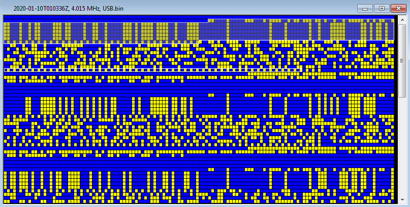
After demodulation, the COMSEC preamble resembles 188-220D std and consists of 3 parts (my guess):
1) 60-bit Frame Sync (110000100000111000101111001011011101101001001011111010101100)
2) 5 x 128-bit strings, encoded Message Indicator (five times repeated)
3) 64-bit idling sequence (time to load the key?)

Preamble is followed by the encrypted data block which ends with "01" sequences.
 
Fig. 2 - demodulated stream of bursts

Fig. 3 - COMSEC preamble (my guess)


https://yadi.sk/d/nY-DTuTz-ZWG8g  (2020-01-10T005300Z, 4.015 MHz, USB.wav)
https://yadi.sk/d/oIHVEWbUO0_few   (2020-01-10T010336Z, 4.015 MHz, USB.bin)

[1] The same modified S4285 waveform was met here on 6931 KHz/usb:
http://i56578-swl.blogspot.com/2018/06/comsec-transmissions-using-s4285.html 

13 March 2019

use of uuencode for email attachments (Swiss-Mil)

This post is an update, mostly a deepening, of the posts published here and here with regards to the way of sending email used by Swiss-Mil. The idea came from a hint from my friend Mike "mco", whom I thank here.

When files, especially email attachments, are transmitted over links that do not support other than simple ASCII data, non-printable characters (for example, control characters) might be interpreted as commands, telling the network to do something. In general, therefore, it is not safe to transmit a file if it contains such characters. UUEncode (Unix to Unix Encoding) is a symmetric encryption based on conversion of binary data (split into 6-bit blocks) into 65 ASCII printable characters (from 32 to 96) and is just used to transmit binary files. 
A message encrypted by uuencode is easily identifiable: it begins with the line 
begin <mode> <name> 
where <mode> is the value of the access rights to the Unix file and <name> is the name of the file that will be created at decoding; the message ends with a line containing only "end". 
An example of the use of uuencode can be seen by analyzing some Swiss-Mil transmissions.
Figure 1 shows the data from a transmission, recorded on 09187.0 KHz/usb, as they appear after the removal of 188-110A overhead (the HF waveform) and the FED-1052 App.B DLP encapsulation (the Data Link protocol).
 
Fig. 1 - email inline attachment sent using UUEncode

Some data of the email are in clear text, in this sample:
ZJ1 root@bfzj1f1.is.bf.intra2.admin.ch, ZJ1 sender
ZA1 statist@bf.intra2.admin.ch, ZA1 recipient
email ID: "stat-ZJ1-20181113135501" (2018.11.13, time: 135501)


The contents are encrypetd using the "IDEA" algorithm (1) [1]:
EncryptionMode=CFB64, Cipher feedback (CFB) mode using 64-bit blocks
IDEAKeyId=20110404
InitialVector=10A2B70A51AACF17, 128-bit Initialization Vector (IV)


The email attachment consists of the (encrypted) block between the lines:
begin 666 /tmp/CFB640250215BEAD7EF13EFAE90.dat
end

that clearly indicate that uuencoding is being used. More precisely, at receive side will create a file named CFB640250215BEAD7EF13EFAE90.dat with access rights 666 in /tmp directory. 


Since in all my samples the uuencoded filenames start with the cipher feedback mode CFB64 (see here) I tend to think that those files are first encrypted using IDEA algorithm then encoded by uuencode, according to the layers shown in Fig. 2.
 
Fig. 2
 

As ending note, it's interesting to notice that this method of message formatting is suggested for any email client or gateway that does not  support MIME and that long before the MIME format  there was just UUEncode. Maybe do they use old not-MIME Unix systems? Do they need to be compatible in all their networks?


(1) IDEA algorithm is developed at ETH in Zurich, Switzerland, and its patents are heald by the Swiss company Ascom-Tech AG. In year 2008 Ascom Security Solutions has been commissioned by Armasuisse (Federal Office for Defence Procurement agency for armaments of Switzerland) to deliver telecommunications equipment as part of the 2007 Armaments Programme.

[1] https://en.wikipedia.org/wiki/International_Data_Encryption_Algorithm

3 September 2018

LINK-11 SLEW, transmission format


The SLEW waveform transmission format consists of an acquisition preamble followed by two or more fields, each field followed by a reinsertion probe. 
The first field immediately following the preamble is the header field and contains information that is used by the Combat Data System (CDS) and the encryption device. If a network PU (Partecipating Unit) has data to transmit, successive data fields follow the reinsertion probe of the preceding fields. These data fields consist of track data and other user data. The last field to be transmitted is the end-of-message (EOM) field. The transmission ends with a reinsertion probe.

Fig. 1

Data are accommodated using 3 different types of fields: header field, CDS data field and EOM field. The acquisition preamble, a very interesting topic, will be discussed in a next post.

The structure of the header field  consists of 33 data bits appended with 12 error detection bits,  H(45,33). The 45 bit sequence is encoded with a 1/2 rate error correction code resulting in a 90 bit field. The header field contains information to define (Figure 2): 
the transmission type T (1 bit),
the Picket address ADDR (6 bits), 
the KG-40 24-bit Initialization Vector (MI), 
the NCS/Picket designation N (1 bit),
a spare field SP (1 Bit).
Fig. 2 - Link-11 SLEW header field
The transmission type (T) indicates the format of the transmission to follow: is set to 0 to indicate an NCS Interrogation Message (IM) and is set to 1 to indicate a NCS Interrogation with Message (IWM) or a Picket reply transmission (the term picket indicates a PU on the network that is not the NCS).
The KG-40 Initialization Vector (IV) subfield contains the sequence generated by the KG-40 crypto device. Cryptographic synchronization is achieved when the receiver acquires the correct IV. Since 24 bits is the length used by the Golay code, I tried to verify if the KG-40 IV was really coded using the extended Golay (24,12) ...but without success. For an NCS interrogation transmission (tramission type subfield = 0), this subfield will contain all zeros since no message is carried.
The address subfield  ADDR contains either the address of the next Picket to be interrogated or the address of the Picket that initiated the current transmission: note that only Pickets addresses are exposed.
The NCS/Picket designation (N)  identifies whether the current transmission originates from the NCS or from a Picket: 0 indicates an NCS transmission, 1 indicates a Picket transmission.

The structure of the CDC data field consists of 48 data bits (two standard 24 bit CDS frames seen in CLEW waveform) appended with 12 error detection bits - H(60,48) - that are encoded with 2/3 rate error correction code resulting in a 90 bit data field. 
The EOM field is used to indicate the end of the transmission and consists of a sequence of 90 bits. No error detection or correction bits are applied to this field. The sequence depends on the unit that is transmitting:
An EOM from the NCS is a 90 bit sequence of all “0”
An EOM from a Picket is a 90 bit sequence of all “1”
Below an example where all the SLEW fields are visible:

100101000110111110001110000011111 000001111100
100010100010001011000001101110010000101011110011 011001011010
111000010110000011110010111001001000000001110000 111100101001
011000001000110111001101100000001100011010110011 001111011101
111001010110100001101001111101011000101011010100 001110110011
111111111111111111111111111111111111111111111111

100101010001100001001000111101001 001101011111
111111010001010101000001001101001111111111101001 001110110000
000111000100111011000110010010001001111110011110 100010111111
001100111011011100100100010000110000001100101110 011101010010
111001100100110100111100010001100010100100011101 100100001111
000000000000000000000000000000000000000000000000

100101001110110010000010101000011 001111010111
100101110000001100001111011000110111011101110111 001111001101
110011011001010000111110011001100101100111110000 011111110010
000111101110101111010000101001011010010100010010 010100001110
100011010110110101111100001110111000011011111010 100010011011
111111111111111111111111111111111111111111111111 


It's interesting to analyze the headers related to the SLEW transmissions shown in Figure 3 

Fig. 3 - SLEW transmissions headers
In all the headers the transmission type subfields (T) are set to 1 to indicate that the following data sub-fields are NCS transmissions or Picket reply transmissions.
In the first header the NCS/Picket designation subfield (N) is et to 0 to indicate an NCS transmission: in this case the 6-bit subfield address identifies the address of the Picket to be interrogated (010100). In the second header the NCS/Picket designation is set to 1 to idicate the Picket reply transmission: in this case the 6-bit address identifies the address of the Picket which initiated the transmission (010100). You may check that
the other headers are interpretable in the same way. So, the headers indicate a series of IWMs and replies between the NCS and the Picket station addressed by 010100.