Showing posts with label WBHF. Show all posts

16 July 2024

MS-110D App.D (WBHF) transmissions, Collins Aerospace over-the-air testing? (2)

Yet another MS-110D sample [1] transmitted from Oxford Junction (IA) site, recorded on 19825.7 KHz/USB and sent me by my friend linkz: this signal too is PSK8 modulated at the symbol rate of 2400 Bd but occupies a 3 KHz bandwidth (Figure 1).

Fig. 1 - waveform main parameters
 
The ACF results  shown in Figure 2 formally show the same characteristics, that is, a sort of "superframe" lasting 840 ms (corresponding to 2016 PSK8 symbols, or 6048 bits) comprising seven frames each lasting 120 ms (corresponding to 288 PSK8 symbols, or 864 bits).
 
Fig. 2 - results from the Auto Correlation Function
 
Bandwidth, modulation and framing match the Waveform Number 7 described in MIL-STD 110D Appendix D (WBHF, WideBandHF)
 

The demodulated bitstreams conform to the bitmaps in Figure 2: in particular, the sequences circled in in Figs. 2, 3 are special mini-probes used to mark the interleaver boundaries. In this case they are transmitted every 64 frames, corresponding to the use of the "long interleaver" mode.
 
Fig. 3 - 864 bits (266+32 PSK8 symbols) period demodulated bitstream

Just to verify compliance with the MS-110D standard, the mini-probes are made up of a repeated sequence of 16 symbols while the miniprobes used to mark the boundaries of the interleaver block are shifted by 8 steps (Figure 4).
 
Fig. 4 - the generic mini-probe and the interleaver marker mini-probe

As expected, the 840 ms spikes resulting from  ACF are due to the cyclic nature of the transmitted data: that is, the same block of data consisting of 7 frames (Figure 5).
 
Fig. 5 - data blocks after the removal of mini-probes

As stated at the beginning, Direction Finding (TDoA algorithm) tests done by my friend linkz indicate Oxford-Junction as the site of the transmitting antenna (Figure 6); more over "It's interesting to note that this data seems to be sent always 22.5 kHz lower than the ALE slots. So far noticed on: 8000.7 USB (8023.2 - 22.5kHz), 18275.7 USB (18298.2 - 22.5kHz), 19825.7 USB (19848.2 - 22.5kHz)" linkz write.
 
Fig. 6 - Direction Finding tests results (thanks to linkz)

https://disk.yandex.com/d/LcwmPMweeu6C0A
 

25 June 2024

MS-110D App.D (WBHF) transmissions, Collins Aerospace over-the-air testing?

Wideband transmission heard a few days ago on 19829.0 KHz (cf) around 1713Z, the recording was kindly sent to me by my friend linkz who also performed - successfully - the Direction Finding attempts (see below).
As from Figure 1, the signal occupies a 6 KHz bandwidth and is modulated using PSK8 at the symbol rate of 4800 Baud. Given that the subcarrier is about 6000 Hz, and it shall be 3300 Hz (300 + 1/2 BW, as usual), the signal should be -2700 Hz shifted (the tuning frequency should be around 19826.0 KHz/USB). 

Fig. 1 - signal parameters

The ACF value and its framing are quite interesting: as can be seen in Figure 2, the autocorrelation plot shows pronounced spykes at 892.4 ms (4284 symbols/12852 bits) due to the existence of a sort of "superframe" consisting of seven frames marked by less evident spikes. The latter have a value of 127.5 ms (612 symbols/1836 bits) consisting of 544 symbols of unknown data followed by 68 (known) channel mini-probe symbols.

Fig. 2 - 127.5 ms & 849.4 ms ACFs

From the above results (bandwidth, modulation and framing) the signal belongs to MIL-STD 110D Appendix D (WBHF, WideBandHF), more precisely the Waveform Number 7: this appendix is a non-mandatory part of MIL-STD-188-110C; however, when data is to be communicated in single contiguous HF radio bandwidths greater than 3 kHz, up to 48 kHz, the waveforms employed shall be in accordance with this appendix. The PSK8 demodulated bitstream is shown in Figure 3.

Fig. 3 - bitstream after PSK8 demodulation

It is worth noting (and verify) some features of this waveform.
As per Table D-XXI the mini-probes consists of a 36 symbol "base sequence" cyclically extended to the required length: in our case, 68 symbols. W/out going into the merits of the mini-probes formation, some resulting mini-probes are shown in Figure 4.


Fig. 4 - 68 symbols mini-probes

In the zoomed bitstream in Figure 5, a characteristic pattern of the mini-probes is seen at intervals of 64 frames: this is because the mini-probes are also utilized to identify the long interleaver block boundary. Indeed, in our case the block length is just 64 frames. The boundary marker is accomplished by tansmitting a cyclically rotated version of the mini-probe (#D.5.2.2).

Fig. 5 - interleaver block boundary

Figure 6 shows the mini-probe marking the long interleaver block boundary: in accordance with Table D-XXI, the mini-probe is formed of the 36 symbols base sequence after 18 cyclic rotations.

Fig. 6
 
As shown in Figure 7, the data block is formed of groups of seven 544 symbol frames (7×544 data symbols) each group consisting of the same data, regardless of the scrambler since the scrambling sequence generator polynomial (x^9 +x^4 +1) is initialized to 00000001 at the start of each data frame (the 511 bits length scrambling sequence is repeated just slightly more than 3 times). The repetitions of these seven groups cause what I designed as "superframe" (see Figure 2) which indeed has a 892.49 ms ACF, corresponding to 7 frames (7×127.5 ms).  Based on the above, it can be said that 127.5 ms is the ACF value of frames and 892.4 is the ACF value of data symbols.
Investigating the nature of these bits does not make much sense since they are actually demodulated "symbols", i.e. data bits after having passed through the modulation chain (FEC encoder, interleaver, Gray decoder, scrambler). The repetitions could suggest a test transmission, but that's just my guess.
 
Fig. 7 - the 7-frame groups that form the data block and that cause the 892.4 ms ACF

As said above, my friend linkz did a great Direction Finding job and pinpointed Oxford Junction (IA) as Tx site location (see Figure 8 below).

Fig. 8 - DF runs (TDoA algorithm), thanks to linkz

The Oxford Junction transmitter site was operated by Rockwell Collins (now part of Collins Aerospace): a paper that they presented at HFIA Meeting in San Diego (February 4, 2010) just confirms the assumption and also shows an aerial photo of the HF station (Figure 9), notice that both EarthExplorer and Google Earth obscured that site.

Fig. 9

Since the Tx location, probably the heard transmissions are WBHF over-the-air test by Collins Aerospace... but that's another guess.

https://disk.yandex.com/d/oj5V4VHl6zb9Gg 

https://www.dropbox.com/scl/fi/4hc6eszz6xvo689b2ah5o/...

7 September 2022

Harris wideband operations (a bit "intruding" within the 7 MHz HAM band)

Wideband activity was heard at the end of August around 7 MHz (figure 1) using mainly Romanian and Greek KiwiSDR receivers, my friend KarapuZ sent me his recordings which are of a much better quality than mine and therefore more suitable for analysis. According my friend, this network was set up around March-April 2022 and is well audible in our area since the network is presumably deployed in the south-east of Europe.

Fig. 1 - wideband transfers

Waveforms, durations and signal sequences in my opinion point to Harris devices: they have in fact developed and implemented  a wide band ALE (WBALE) adaptive system that selects the best channel, the available bandwidth and the frequency offset required for optimal wideband communications [1]. As I already mentioned in some blog posts, Harris WBALE relies on 3G-HF STANAG 4538 Fast Link Setup (FLSU) to establish a wideband link:

- the calling station first places a call using STANAG 4538 FLSU to exchange profiles of the two linking radios’ and and negotiate a traffic waveform
– the standard FLSU Request PDU has a traffic type parameter; Harris uses a new value of this parameter (reserved but not defined in  STANAG 4538: see table 4.6.1-2 "second 6-bit argument field") to indicate that a wideband link is to be established
- the radios then use an additional handshake (not defined in STANAG 4538) to negotiate bandwidth and offset (from the assigned frequency, see figure 1) to be used, based on the results of the preceeding "spectrum sensing"  (1).

Figure 2 shows the timing diagram of all the signalling required for the Harris WBALE protocol: the timing diagram follows the one described in 188-141D App.G, even if the used waveforms are different!

Fig. 2 - wideband session timing and real-world wideband transfer
 

Traffic is exchanged using Harris proprietary WHARQ waveforms family, quite well recognizable by their "superframe" consisting of a STANAG-4538 BW6 preamble followed by 8 frames each characterized by a different miniprobe pattern.  An ACK PDU is transmitted by the receive station using a BW6 burst waveform. Figure 3 shows the main parameters of the WHARQ 2400 Bd 3-KHz bandwidth waveform.

Fig. 3 - WHARQ 2400 Bd 3-KHz bandwidth waveform

As I titled, the problem lies in the fact that one of the WB channels occupies about 12 kHz of the low part of the 7 HAM MHz band. It must be said that the 7 MHz band is primarily assigned to radio amateurs, however also shortwave broadcasters and land mobile users have primary allocations in some countries so amateur stations must share bandwidth with these users. 

The choice of the 7 MHz for such milcomms is probably related to the "primary and secondary users" concept [3] which divides the users into primary users (licensed) and secondary users (unlicensed): the first “own” the bandwidth allocation while secondary users are only allowed to use this spectrum in a non-interfering basis:

a) for WBALE primary user mode, stations that link for the purpose of transferring data will use a bandwidth and offset in each direction that is chosen to maximize the signal-to-noise ratio (SNR) with which transmissions in each direction are received. Stations will avoid interference with other stations within the same network, but will make no effort to prevent interference with other stations outside the network, except as a byproduct of optimizing communications within the network.  This can have at least two significant implications:
1. the bandwidth and offset used in each direction of the link may be different;
2. the stations may cause harmful interference to communications in other networks while themselves not experiencing harmful interference. 

b) in secondary user mode, WBALE stations will not (as far as is practical) cause interference to other stations outside the network that are operating within the same channel allocations used by the network. In particular, whenever a link is established for a wideband data transfer, the bandwidth and offset used for the link will be chosen so as to avoid interference with any transmission detected by either side. This is likely to require that the same bandwidth and offset be used in both link directions.  

As you may see in figure 1, the bandwidth and offset used in each direction of each logical link are the same, threfore, in my opinion, it seems that they use this portion of band (7 MHz) in secondary user mode.

Fig. 4 - a Rockwell Collins modem performing the spectrum sensing (2)

(1) To effectively utilize the allocated bandwidth, WBALE will need to listen to an entire wideband channel of up to 24 kHz, detect the presence of interfering signals on the channel that could render all or part of the channel unusable, and identify any portion of the channel that may still be usable even if the channel is partly blocked. This function is referred to as "spectrum sensing".

2) Initial Wideband ALE developing and testing was condected togheter by Harris and Rockwel Collins.
 
 
[3] William N. Furman, John W. Nieto, Eric N. Koski: The 10th Nordic Conference on HF (2013)
 

8 January 2021

Fast WALE (4G-ALE) and wide band traffic (WBHF)

Thanks to a reporting of my friend Martin G8JNJ, on 4744.0 KHz - mostly in the morning -  it is possible to receive transmissions which use Fast WALE (188-141D App.G) and WBHF (188-110D App.D) waveforms: it's the first time for me that I have the canche to "see" and analyze 4G-ALE signals. 

The WALE (4G-ALE) system uses waveforms derived from the WBHF waveforms for its transmissions, and draws ideas from both second and third-generation ALE for its protocols. The WALE waveforms operate in 3 kHz and provide two interoperable modes for sending PDU: the “Fast” WALE waveform (intended for very fast link setup in voice-quality channels) and the “Deep” WALE waveform (designed for operation in the most challenging channels, including SNR < 0dB). The choice between Fast or Deep WALE can be made on a call-by-call basis as receivers listen to both types of WALE calls, as well as 3G & 2G ALE calls for simultaneous operation with existing narrowband circuits.[1]

In the recorded session shown in Figure 1, the transmissions consist of two-way WALE handshakes followed by data transfers using ARQ method and WBHF waveforms: the bursts following the last ACQs are probably an EOM signaling given that the following session begins with a WALE handshake. Since the strong signals in the analyzed sample, I can't say if it's a bidirectional link. 

Fig. 1

The WALE LSU protocol use a fixed 96-bit length PDU for both Fast and Deep waveforms with a correction coding consists of a constraint length 9 (CL-9), half rate convolutional code producing a 192-bit coded block (ie, for each bit input to the encoder, two bits are taken from the encoder). Using Fast WALE the coded and interleaved bits of each PDU are sent in alternating blocks of unknown (data) symbols and known (probe) symbols.

The WALE waveforms employ PSK8 modulation of an 1800 Hz subcarrier at a rate of 2400 symbols per second. The two more dense states in the phase plane of Figure 2 are due to the BPSK modulation of  Fast WALE data.

Fig. 2
 

In the analyzed samples the portion before the coded and interleaved PDU, according its 83.33 ms duration, consists of 200 PSK8 symbols (figure 3). Since the preamble and the TLC sections use the same 32-element Walsh chips (32 PSK8 symbols), the initial portion consists of 1 TLC block (13.333 ms) followed by 168 PSK8 symbols (70 ms) which do not resolve into an integer number of 32-element Walsh chips! These values, durations and symbols, are not compliant with relevant standard (188-141D #G.5.1.8.2) which requires nine 32-element Walsh chips for the Fast WALE  preamble, for a total of 288 PSK8 symbols and a 120 ms duration.

Fig. 3

The structure of the known/unknown symbols blocks is exactly compliant with 188-141D: ie, 288 PSK8 symbols and a 120 ms duration (figure 4). Notice that according 188-141D, the length of the preamble shall be equal to the sum of the lengths of the known/unknown symbols blocks.

Fig. 4

The traffic waveforms are PSK8 modulated at symbol rate of 9600Bd, ACF value is 120ms that makes a 3456-bit length period or 1152 PSK8 symbols (Figure 5): the frame structure (Figure 6) matches the waveform #7 of 188-110D App.D ie, 1024 Unknow symbols (3072 bit) + 128 Known symbols (384 bit). 

Fig. 5 - WBHF waveform #7

Fig. 6

The bursts I termed as "EOM" also employ PSK8 modulation at symbol rate of 9600 Baud and have a frame length of 1504 symbols (Figure 7).

Fig. 7

[1] https://www.rapidm.com/wp-content/uploads/2018/10/RM10_WBHF_EN.pdf

https://yadi.sk/d/FkvzXFHKLL0Rbw

21 September 2020

48 KBaud OQPSK unid wideband transmissions


This post originates from an email from my friend KE9NS Darrin who noticed  a strange transmission around 6.8 MHz with an occupied bandwidth of about 48 KHz. According to his reports, the signal seems to start somewhere between 0000 and 0100 UTC, likely ON until sun rise. Interestingly, the signal tends to move around the band slightly probably trying to find an open slot in the band. Indeed, some breaks were observed and Darrin just noted that when it shut down for a break there was a STANAG 4285 signal within its 48 KHz passband: it must have realized and moved to an open spot.
Darrin kindly sent me his IQ recordings for analysys since it's impossible for me to get such samples using remote KiwiSDRs.

The waveform has a speed of 48000 Baud and occupies a band of about 48 KHz: as shown in Figure 1, the spectrum width, equal to the manipulation speed and the presence of the third line in the 4th power, lead to think to the Offset QPSK (OQPSK) modulation.

Fig. 1
Although GMSK and OQPSK have a lot in common, some further clues in favor of OQPSK come from the phase plane (Figs. 2a, 2b): OQPSK looks like GMSK with BT < 0.25 (the lower the BT index, the more it's similar to OQPSK).

Fig. 2a - OQPSK phase plane

Fig. 2b - syntesized OQPSK signal
 
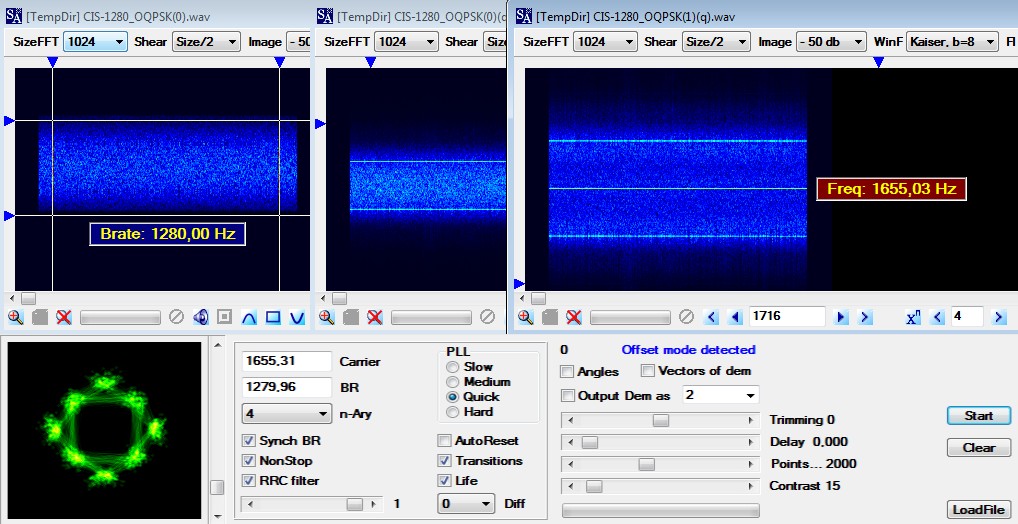
Similar results were obtained from the analysis of CIS-1280 waveform (Figure 3).
 
Fig. 3 - CIS-1280 OQPSK waveform

OQPSK is a constant-envelope modulation that has no 180-deg phase shifts and, therefore, has a much higher spectral containment than non-offset QPSK when transmitted over band-limited nonlinear channels. To further bandlimit an OQPSK signal, Shaped OQPSK (SOQPSK) was introduced and its initial version was referred to as MIL-STD SOQPSK after it was adopted as part of a military standard. 
 
Since OQPSK is like a GMSK with a small index, it is possible to do some demodulation attempts using the "FSK3 method" introduced by guys from radioscanner.ru [1]. In this regard, I also tried that FSK3 method by demodulating the 48 KBaud signal on three FSK levels (Figure 4) and then appropriately converting the ternary symbols through a small program written with Octave. It is difficult to establish the accuracy of the final bitstream, anyway the links to download the intermediate FSK3 file are below: everyone can try the demodulation by following the method described and post their comments and the obtained bitstreams.

Fig. 4 - FSK3 demodulation

Back to the 48 KBaud signal, it's always very strong, likely a very powerful transmitter. Quoting Darrin "Its a long shot but, the company that was supposedly trying to transmit stock trades via HF radio has a radio tower located in a town near to me. Supposedly they have a huge antenna array in Elburn, IL and transmit 20kw with an ERP of 808kw (very big stacked curtain log-periodic antennas) pointed 48deg and a special FCC license. It turns out, that antenna array is pointed directly towards my home in Bartlett, IL". We also thought of 188-110D App.D (per STANAG-5069) tests but such a waveform is not indicated.

https://yadi.sk/d/J76M1y-l-u42Sg (wav file) 
https://yadi.sk/d/_3o-UTVKEQpKNw (FSK3 demod)

[1] http://www.radioscanner.ru/forum/topic43183.html#msg865791

12 February 2020

Interesting MS-110D App.D (WBHF) traffic


Interesting traffic heard on 5750 KHz/USB and picked up thanks to the UK KiwiSDR owned by G8JNJ.
Most of the signals are definitely "110C Appendix D" 3 KHz BW waveform (WID 1 or 2, BPSK). The synchronization preamble has a framing of ~240ms length that makes 576 symbols @2400Bd speed (Fig. 1). From 188-110C App.D documentation, the orthogonal Walsh modulation is used in the synchronization section of the preamble and the length of the repeated super-frame is 18 channel-symbols, ie: 9 (fixed) + 4 (downcount) + 5 (waveform identification). Since in 3 KHz bandwidth waveforms the preamble channel-symbols are 32 symbol long, the length of each repeated superframe is: 18 (channel-symbols) x 32 (length of one channel-symbol) that just matches the measured 576 symbols length.
Data section has 40ms length frames (Fig. 2) i.e. each frame consists of 96 symbols: 48 unknown data + 48 known data (mini-probe). This framing meet the waveform IDs 1 and 2 of the 3KHz bandwidth set (BPSK modulated data).

Fig. 1 - Synchronization preamble superframes
Fig.2 - data section frames
Anyway, FLSU BW5 bursts and unid 2400Bd bursts are the most interesting aspects in this catch.
In my opinion the presence of (repeated) 3G-HF Fast Link SetUp (FLSU) BW5 bursts is rather strange also because the link seems to be terminated with a 188-141A 2G-ALE "TWS" sequence: a kind of "fall back" for 2G-ALE? Perhaps we're dealing with a STANAG-4538 "circuit-mode" service and I did not hear the BW5 PDUs sent by the other side of  the link, or perhaps BW5 PDUs are just used to signal the following traffic waveform.
The other 2400Bd bursts (Fig. 3) have a fixed duration of ~2840ms: unfortunately the poor SNR of the signals does not allow to get other significant parameters from their analysis.

Fig. 3
As said, the link was terminated using 2G-ALE: the TWS message was sent by the ALE callsign "AC7", It's to be noticed that during the monitoring period other ALE soundings from calls "AC7" and "AC9"  have been heard. According to recent UDXF logs, these calls refer to a unid Jordan network, although it sounds weird to me that they use WBHF technology. Maybe some WBHF trials... but it's just a guess.

southwest.ddns.net_2020-02-06T21_02_31Z_5750.00_usb.wav
southwest.ddns.net_2020-02-06T20_56_47Z_5750.00_usb.wav

16 April 2019

Harris wideband operations, WHARQ and WBALE waveforms (2)


Recently we had the chance to monitor and record the wideband transmissions on 7.9 MHz thanks to the use of four fairly close together KiwiSDRs [1] (we think transmitters use low power and NVIS) and this allowed us to have a better understanding of the whole scenario.
The data waveforms occupy a bandwidth from 3 to 24 KHz (grouped together under the title, courtesy of radiofrecuencias.es) and use an adaptive ARQ pattern with modulations from PSK-8 up to QAM-64. As said, most probably they are part of the Harris WHARQ development: a proprietary wideband HF waveforms family, already discussed here and
largely discussed by my friends ANgazu, Malak and Rapidbit in radiofrecuencias forum [2]. The burst waveforms are the WBALE PDUs, i.e. the Harris design choices for the implementation of 188-141D extensions for 3GWB mode [3]. 
 
Fig. 1 - spectrogram of a WHARQ waveform (credits to ANgazu)
WHARQ waveforms have a preamble/header followed by slots of miniprobe and data, 8 slots make a frame (or 8 frames grouped into a super-frame). Header modulation is always PSK-8 and it's followed by a "double" miniprobe. The duration of the header relies on the speed of the waveform (baud rate) and not depends on the used modulation. Frame is made up by 8 slots (data + miniprobe) consisting of 8 different miniprobes for each frame. ACF varies depending on modulation and baudrate. For further details on WHARQ I suggest to read the relevant posts and analysis in radiofrecuencias forum, here I focused on the WBALE bursts.

A quite clear WBALE/WHARQ scenario is visible in the IQ recording below in Figure 2:

Fig.2
The upper bursts are 3G STANAG-4538 BW5 and BW6: BW5 is used for Fast Link Setup (FLSU) and BW6 used as acknowledgemts PDUs. Lokking at these samples, in my guess it seems that BW6 ACK is used with 3 KHz WHARQ waveforms and a proper WHARQ ACK burst is used with wider waveforms. 
Harris approach for 3GWB is based on a simple enhancement to the Fast Link Setup protocol defined in STANAG 4538. The primary modification is the use of an additional 3 kHz bandwidth burst handshake (WBALE HS in Fig. 3) which exchanges profiles of the two linking radios' locally measured interference environments and negotiates a waveform bandwidth, offset from the specified channel frequency, and modulation and coding selection suitable for reliable high-performance communications.

Fig. 3 - Harris WBALE (not in scale!)

The WBALE handshakes are clearly visible in Fig. 4, it's worth noting the change of the traffic waveform after bandwidth negotiation:

Fig. 4 - WBALE handshakes

WBALE PDUs are very similar to BW5 FLSU PDUs so I analyzed them using a 3G demodulator: the following are therefore my hypothesis that need further confirmations.
 
Fig. 5 - WBALE waveform
The PDUs have a duration of 525ms and consist of 1216 PSK8 (2400Bd on-air) symbols: 256 PSK8 symbols (768 bits) for the preamble which is followed by 960 PSK8 symbols (2880 bits) for the ALE payload. I don't know, though it's likely, if the preamble is preceded by one or more short TLC blocks (they might be ignored by demodulator). Since Harris WBALE it's 3G based, i.e. network participiants are synched, I do not think to "variable" length PDUs to best fit the scanning lists: there is no need since the peers are already linked by the previous BW5 FLSU handshakes (this means that WBALE bursts are not "caller" PDUs!).

1216 symbols @ 2400Bd are well suited to the duration of 525 ms
After a raw PSK-8 demodulation the payloads show a 3-bit structure (Fig. 6) and are possibly modulated using a Walsh function: it's difficult to establish the actual length of the payload since FEC coding and Walsh format info missing (by the way, payloads could be descrambled using the polynomial x^4+x^3+x+1 to obtain a 12-bit stream... but it's just a speculation!).  

Fig. 6 - payload 3-bit structure after raw psk8 demodulation

15 March 2019

Harris WB operations and UK MoD XMPP over HF: interesting confirmations

Reading the Harris and Isode-Babcock presentations at the recent HFIA Meeting in San Diego, CA (February 14, 2019) I had an interesting feedbacks which could confirm the guess I did about:
1) new wideband HF waveforms tested by Harris (the analysis is posted here)
2) XMPP chat over HF by UK MoD (the analysis is posted here).


1) In the Harris presentation "Summary of Harris on-air testing of WBHF systems 2010-2018" you can read that since 2015 Harris began development of a WBHF Hybrid Automatic Repeat Request (ARQ) waveform for use on HF (WHARQ). It supports 3, 6, 9, 12, 15, 18, 21, 24 kHz. WHARQ is bundled in a new radio mode called 3G Wideband IP (3GWBIP) which has been tested extensively on the bench and over the air. On-air 3GWBIP testing took place on november-december 2018 using NVIS link and 150 Watt power.


As posted here, me and some friend of mine saw 3-24 Khz bandwith waveforms with modulations from PSK-8 to QAM-64 and data rates from 75 to 120,000 bps. Although the characteristics such as BWs, modulations and speeds are the same as those indicated in Appendix D of MIL-STD 188-110D (WBHF), these adaptive waveforms definitely do not belong to that standard. 
Maybe we just hear those WHARQ/3GWBIP waveforms?


2) in the Isode-Babcock presentation "UK Mod XMPP over HF Pilot" you find that UK MoD Funded Babcock to run an XMPP over HF trial using Isode XMPP Software. “Group Chat” provided by XMPP Multi-User Chat (MUC) is the core service Highly desirable to use Real Time Chat for Naval and Airborne communication when HF is the only available bearer. In the paper they presentred the trials run to evaluate viability of providing this service over STANAG 5066 ARQ.


Well, I'm happy to see that this paper matches the results posted here
.