Showing posts with label FLSU. Show all posts

18 March 2024

3G-HF Fast Traffic Manager (FTM) at work

This sample provides an example of the use of 3G-HF (STANAG-4538) Fast Traffic Manager (FTM) protocol, which is sometimes referred to as simply FLSU (Fast Link SetUp). More precisely, FLSU is used to set up links, and it includes the traffic type that will be used immediately after the link set up is complete; FTM is used after the FLSU for cases in which the traffic type needs to be changed, or to negotiate channel access among linked stations.
As stated in S-4538 Annex-C Edition1 Amendment2, if a link has been established for delivery of packet traffic using the HDL+ data link protocol (BW7), all FTM and FLSU Protocol Data Units (PDUs) transmitted for the remaining duration of the packet link shall be transmitted using the BW6 burst waveform: thus, since the use of BW6, the link was initialized for HDL+ protocol. But, as you can see in Figure 1, at some point an FTM negotiation causes the change of the traffic type: from HDL+  (BW7 waveform) to LDL (BW3 waveform).

Fig. 1 - traffic type change

It's worth noting the use of BW4 waveform bursts after LDL data delivery, it's requested by the #4.6.5 Dual Demodulation condition: "Under no circumstances shall stations be required to simultaneously demodulate more than two waveforms. Any scenario requiring more than dual-demodulation is either an error in the specification or an error in interpretation" (1).

 
By the way, the BW3 burst transports a L3Harris "Citadel" encrypted message (Figure 2).

Fig. 3

https://disk.yandex.com/d/YCupV-cFBXOmqQ

(1) HDL+ states is missing in the Table 4.6.5-1: however, since BW6 burst waveform is used for Ack/EOM/Term messages, Master and Slave stations expect to receive a BW6 or a BW7 waveform.

24 October 2022

Harris' 3G-ALE FLSU Async call (2)

Commenting the recent post about the Harris's implementation of the FLSU Async call [1], an anonymous reader sent me a good quality recording of that signal. Observing the spectrum/time FFT of figure 1 the call has a duration of about 9 seconds (9170 ms) and, according to the value of the ACF , it consists of 10 BW5 frames. By calculating the respective durations and taking into account the omission of the TLC sections exceeding the first, we get

1013.33 + (9 × 906.66) = 9173.27 ms

ie a value that matches the duration of the call and confirms the FLSU Async call implementation adopted by Harris (by the way, a 7-channel scan list in this sample).

Fig. 1

In addition to the time based approach, in order to verify the above results I tried a tribit symbols based analysis of the demodulated bitstream. Indeed, as per STANAG-4538 (and 188-141B too) the TLC section (256 pseudo-random tribit symbols) and BW5 preamble sequence (576 tribit symbols) are modulated directly without undergoing the PN spreading thus their patterns are easily identifiable within the bitstream. A good way to bring out the two desired sequences is to use synchronization of the bitstream:

a) synchronizing on the preamble sequence
10 rows come out, which therefore correspond to the preambles of the 10 BW5 PDUs (don't fall into the 4-bit HEX trap: since the PSK8 modulation, the symbols we are looking consist of tribit values, ie 4,4,7,3,... = 100, 100, 111, 011,...):

Fig. 2

b) synchronizing on the TLC sequence
as expected, the result consists of only 1 row which is just the one relating to the "entire" first BW5 PDU:

Fig. 3

As a further confirmation, I synchronized the stream on the "border" of the two sequences getting a single row result:

Fig. 4

So, in my opinion, both approaches demonstrate the composition of the FLSU Async call which is implemented by Harris: ie, the TLC section is sent only in the firts BW5 PDU (as per 188-141B #C.5.2.4.5.2):


Looking at the bitstream, it's also  evident that this network uses the Linking Protection (LP) procedure [2]. As per STANG-4538 #9.3.2 "Scanning call PDUs shall be scrambled using alternating word numbers 00000000 and 00000001. The word number used in scrambling the first scanning call PDU shall be selected so that the scanning call PDU sent immediately before the Call PDU is scrambled using word number = 00000001. The Call PDU that concludes an asynchronous-mode call shall be scrambled using word number = 00000010": that's the reason of the alternating patterns of figure 5.
 
Fig. 5

By the way, it's worth noting that LP does not address jamming or similar techniques, which are best countered by TRANSEC, nor is it intended to replace the COMSEC function of traffic protection: indeed, LP protects the linking function, including related addressing and control information.
 
A recent monitoring of 6.9 MHz band by my friend ANgazu (who I thanks for sending some recordings) shows the use of the same async call also in WBALE & WHARQ scenarios:
 
Fig. 6
 

10 October 2022

Harris' 3G-ALE FLSU Async call: a 141B/STANAG-4538 optimised implementation?

I recently had the chance to study some good quality recordings of (certified) Harris 3G-ALE Asynchronous calls and surprisingly I found some features of implementation derived from the now superseded 188-141B that are not defined - or even not supported - by the relevant standard STANAG-4538.

More than once I came across such type of "long duration" FLSU bursts and so far I have always identified them as FLSU Asynchronous calls (STANAG-4538) [1][2] ...but this time it is not like that. What doesn't fit is that while each burst 2-4-6 consists of a single FLSU BW5 PDU (Protocol Data Unit), as expected, also the bursts 1-3-5, although of longer duration, seem apparently formed of single FLSU BW5 PDUs (figure 1).

Fig. 1 - Harris 3G-ALE bursts

A short recap for background... 

As per STANAG-4538 #5.1.3, the Asynchronous call consists of a "sequence" of FLSU PDUs sent consecutively, more precisely:
"The Asynchronous call begins with the LBT [...] followed by the transmission of about 1.35N Async FLSU_Request PDUs on the requested link frequency, where N is the number of channels in the scan list, and 1.35 is the duration of each dwell (in seconds) [...] the sequences of the Async FLSU_Requests (Type-3 PDU) is then terminated by one normal FLSU_Request (Type-0 PDU)"(1):

Fig. 2 - Asynchronous FLSU call (1) (FIGURE 5.1.10-4 STANAG-4538)

Therefore, the Async FLSU call is easily reacognizable by the 1013ms "spikes" (ie the duration of the BW5 PDU) resulting from its Cross-Correlation Function. Obviously, the 7296-bit (or 2432-tribit symbols) period of the bitstream matches the PSK8 symbols of the BW5 waveform. Figure 3 shows the CCF and the bitstream of an Async call recording ( the .wav file is in the download list).

Fig. 3 - CCF and bitstream of the FLSU Async call

The 50-bit frames resulting from its demodulation (fortunately Linking Protection was not used) are consistent with the standard protocol. By the way, since the 10 Type-3 PDUs, the scan list consists of 8 channels.

 
That said, let's back to the Harris 3G-ALE recordings.

The Cross-Correlation Function of bursts 1-3-5 shows strong ~906ms spikes instead of the expected 1013ms ones, consequently the demodulated bitstreams have a 6528-bit period length which in turn makes 2176 PSK8 symbols: so, we have  
 
(2432 - 2176) = 256 missing symbols

Fig. 4 - CCF and bitstream of the Harris FLSU Async call

Looking at the BW5 timing, the initial TLC section consists of 256 PSK8 symbols: well, these are exactly the symbols that we are looking for! 


I mean that the TLC section is sent only in the first BW5 PDU thus the following ones are a bit shorter being composed of only the preamble and data sections: hence the (576 + 1600) = 2176 symbol length period and the ~906ms CCF spikes. This "formation" of the Async call also clarifies why my decoder recognizes only the "first" BW5 PDU (figure 1). By the way, the value 

1013.33 + (5 × 906.66) = 5546.63ms 

fits perfectly in Harris recordings.

Fig. 5 - formation of the Harris FLSU Async call

Such a call is exactly described in paragraph C.5.2.4.5.2 of  MIL 188-141B Appendix C:
"The LE_Scanning_Call PDU shall be sent repeatedly to capture scanning receivers [...] During a scanning call, only the first LE_Scanning_Call PDU shall include Ttlc (used for transmitter level control and receiver AGC settling). All succeeding LE_Scanning_Call PDUs and the LE_Call PDU shall omit Ttlc, and include only the BW0 preamble (Tpre) and data (Tdata) portions".(2)(3)

So, we face a STANAG-4538 FLSU Async call (since the use of BW5 waveform) which is 188-141B compliant for what regards its formation (since the omission of  the TLC sections): ie, a sort of  188-141B/STANAG-4538 mixed implementation. Below I have tried to find a satisfactory answer to this "particular" 3G-ALE call.

For simplicity and clarity of exposition, for now on I will refer to:
- "188-141B" as an FLSU Async call with omitted TLC sections (only the firts one is sent);
- "STANAG-4538" as an FLSU Async call w/out the omission of the TLC sections;
the FLSU protocol obviously implies the use of BW5 PDUs.

One could say that, given the nature of the TLC section (basically 256 throwaway symbols), sending it in a sequence of contiguous BW5 PDUs would makes a poor sense... but that's not entirely true. It is possible to verify that, starting from a certain number of channels onwards, the TLC sections act as a "buffer" and, ultimately, allow a successfully link establishment. Indeed, defining "scan time" the interval of time required for scan N-1 channels, linking is successful as long as the scan time does not exceed the duration of the Async call (figure 6).

Fig. 6 - "scan time" Vs Async call duration

Suppose we have a 21 channel network: the worst case that can happen is that a 141B async caller begins a call on the last channel of the scan list (after a successful Listen Before Transmit interval) while the called station has just begun to dwell on the first channel. Let's calculate how many PDUs must be sent in the call:

1.35 × 21 = 28.35 ≅ 28 Async FLSU_Request PDUs + 1 normal FLSU_Request PDU

for a total duration of (including the initial 1350 milliseconds LBT interval):

1350 + 106.66 + (906.66 × 29) = 27749.8 ms.

The called station will employ (20 x 1350) = 27000 ms to come upon channel 21, so it will receive only a portion of  (27750 - 27000) = 750 ms of the Async call: this means that a part of the acquisition preamble of the final FLSU_Request will be lost and presumably the linking attempt will fail or at least will be at risk. Such a problem will not happen in case of a STANAG-4538 async caller, since its call will last:

1350 + (1013.33 × 29) = 30736.57 ms

therefore the called station will receive a quite large portion of about (30736.57 - 27000) = 3736.57 ms of the Async call (ie more than 3 times the duration of a BW5 FLSU PDU).(4)

I plotted the durations of Async calls and scan times versus a scan list of 5 to 30 channels: the results are quite interesting (figure 7). In case of 141B, starting from channel 16 the distance between the duration of the call and the scan time is getting thinner, until it becomes null or even negative. STANAG-4538 implementation instead maintains a quite wide margin (figures 7a). Then I plotted the the difference (async call duration - scan time) referred to the "useful" duration of a BW5 PDU ( 906.66ms, ie preamble + data): say a sort of measure of the "linking useful margin" versus the number of channels. In case of 141B calls, as expected, the linking gets problematic starting from a 16-channel scan list (figure 7b); no problems in case of S4538 calls (figure 7c).

Fig. 7

Well, how many channels can be allocated to a scan list? Looking at the framing of BW5, the "Argument 1" field reserves 6 bit for the channel; excluding the default value ("111111"), 63 values (0...62) remain available. As it was already evident from figure 7, a 141B Async call does not capture the called station in case of such a large number of channels but - conversely - it's best performing then STANAG-4538 in a network with a smaller scan set (number of channels < 17) just because it has a shorter call duration and therefore a faster linking time (figure 8).

Fig. 8

Probably the Harris' choice of omitting the exceeding TLCs just lies in the fact of better performance in small scan lists (say an "optimised" implementation): perhaps a specific algorithm chooses whether or not to omit the TLCs exceeding the first, or perhaps it's a manual setting. That solution is anyway not compatible with the 188-141B implementation (BW5 is unknown to that standard) and probably also with a "strict" implementation of STANAG-4538: the unanswered calls in figure 1 could be a sign of interoperabilty problems (5), who knows. Judging by the behavior of my decoder, however, I verified that in case of a "late entry" the decoding is successfully only when the Async call contains multiple TLCs: but it's just a decoder, I don't know the algorithm it uses and doesn't matter. Unfortunately I don't have a military grade STANAG-4538 appliance to test its responses, so further analysis are needed to confirm my guess.

I want to thank my friend ANgazu who helped in the analysis and identification of the signal and sent me some recordings of these "mixed" Async calls that he heard just some days ago around 6950 KHz: sign that this solution is still in use today.

https://disk.yandex.com/d/xbGLZvU5y5A1Qg 188-141B FLSU Async call (single TLC)
https://disk.yandex.com/d/gXsMejYAvHFstA   S4538 FLSU Async call (multiple TLCs)
(regarding the Harris recordings, the author prefers that I keep this material confidential)

Some ending comments:

a) I played Lego ® bricks with the burst #1 of the Harris recordings. Using the great tool Audacity ® [3] First I isolated and removed the TLC section of the first BW5, then I did my best by cutting the burst into segments each of 906.66 ms duration. Then I assembled a new burst by inserting the TLC section before each segment and putting it all together. The result confirms the expectations, apart from two error PDUs due to the approximate way of the cut & paste. By the way, five scanning PDUs mean 4 channels in the scan list.

b) You've probably noticed the possibility of a 768-bit/256-symbol period in figure 4:


As per STANAG.4538 #13.9.6, the BW5 PDU data symbols are PN-spread using a spreading sequence which is repeated every 4 blocks of 64 tribit sequences, ie every (64×4) = 256 symbols: these repetitions cause the 106.66ms ACF and hence the 256-symbol periodicity:

 By the way, yet another 106.66ms ACF...

(1) Transmitting 1.35N Async FLSU_Request PDUs guarantees that all other scanning PUs (Partecipating Units, ie the other nodes in the HF network) will scan the calling channel during the Async call, even under the worst case time of day offset conditions. If the time of day offset can be estimated more accurately, fewer than 1.35N Async FLSU_Request PDUs may be sent to capture the desired PU. Since the address of the called PU(s) is contained in the Async FLSU_Req PDU, all PUs that are not included in the call are free to resume scanning. Called PU(s) that receive one of the Async FLSU PDU’s stop scanning and wait for the normal FLSU_Request.

(2) MIL 188-141B refers to BW0 as the waveform to convey "LE_Scanning_Call PDU" and "LE_Call PDU" (LE stands for Link Establishment): FLSU, and consequently the BW5 waveform, were not yet defined at that time. 

(3) 188-141B (released on March 1999!) was superseded by 188-141C (December 2011), in its turn superseded by 188-141D (December 2017): the last two standards no longer have the Appendix C but only some short paragraphs, among them the #C.6 says "The specifications previously contained in this appendix have been replaced with reference to the essentially identical NATO STANAG 4538".

(4) The Called station that receive one of the asynchronous FLSU PDUs stop scanning and wait for the normal FLSU_Request PDU, which is sent immediately after the final Async_FLSU_Request PDU. After receiving a valid FLSU_Request PDU, the addressed stations responds normally with the FLSU_Confirm PDU (STANAG-4538 #5.1.3)

(5) The BW5 bursts 2-4-6 of figure 1 may convey the FLSU_Terminate link PDU (type-2) which is sent by the caller station in case of link failure (STANAG-4538 #5.1.5). Unfortunately, Linking Protection is used so the decoding does not help to indentify the used BW5 types.

[1] https://i56578-swl.blogspot.com/2019/10/async-flsu-followed-by-stanag-4197-3g.html
[2] https://i56578-swl.blogspot.com/2021/04/a-long-and-protected-flsu-async.html
[3] https://www.audacityteam.org/download/

26 June 2021

3G-HF "BW5 + 110A" combined waveform ...or just coincidence?


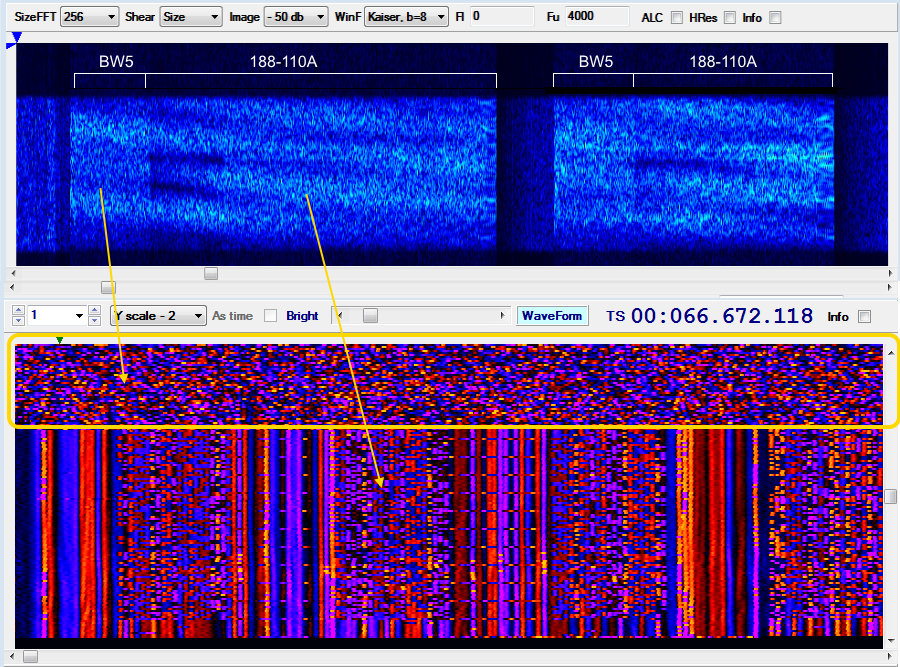
From 19 to 23 June I monitored interesting transmissions on 5091.5 KHz/USB that seem to use a kind of "combined" waveform which consists of FLSU BW5 waveform followed by 188-110A 300bps waveform. For what concerns the timing, the sendings occur each minute, they last about 31 seconds and are arranged in a way that resembles the circuit mode service of STANAG-4538. Starting from thursday 24, these broadcasts have not been repeated (at least until today).

Fig. 1 - ACFs  


As said, it seems that the data are sent using a transmission composed of two parts: a sequence of FLSU PDUs, which are transmitted using the BW5 burst waveform, and the payload data, transmitted using the 188-110A serial waveform. These two parts are transmitted contiguously with no dead time separating them (Figure 2).

Fig. 2 - framing

That kind of waveform (BW5 + 110A) is indeed very odd, unless I have been mistaken and it is an overlapping of two distinct transmissions... but it would still odd that the overlapping be so perfect and continuous for more than two days.  Anyway, if it's a real "combined" waveform then it's definitely a synthesized waveform (SDR).
For clarity - however - it must be said that:
a) BW5 waveform (and thus the FLSU protocol) has been detected by the examination of the signal's ACF and its payload;
b) the length (duration) of the initial BW5 sequence finds a clarification in this post;
c) BW5 waveform could also be used to transport other types of PDUs and not only the PDUs of the FSLU protocol.

data link protocol
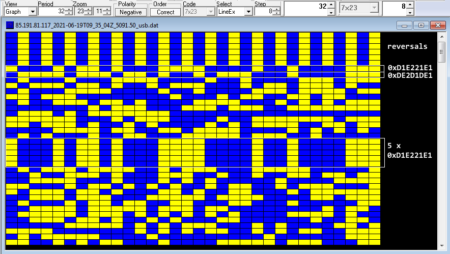
The used data link protocol is also interesting: its initial structure consists of 32-bit (4 bytes) patterns which are common to all the payloads (Fig. 3):

192-bit idle sequences of reversals (alternating sequences of '0's and '1's)
10001011010001111000010010000111 (0xD1E221E1) sequence #1
01111011101101001011100010000111 (0xDE2D1DE1) sequence #2
11 bytes length data block
10001011010001111000010010000111
10001011010001111000010010000111

10001011010001111000010010000111 (5 x sequence #1)
10001011010001111000010010000111
10001011010001111000010010000111

(data block follows)

Fig. 3 - data link protocol after 188-110A removal

The two 4-byte sequences are not originated by polynomials and are likely used as sync patterns, although the five repetitions of the sequence #1 lead to think to an Initialization Vector; in my opinion, a such method could be risky in terms of security since the same IV sequence is used for all the forwarded messages (unless they are test transmissions and/or pseudo random traffic). Data blocks seem anyway encrypted.

Fig. 4 - details of the 32-bit structure of the data link protocol

The exact same structure and 32-bit sequences have already been detected in some recordings of 2018 (!): also in this case they were "plain" 188-110A transmissions forwarded in circuit mode service [4].

TDoA direction finding
The transmissions are fairly receivable only in the northern regions of Europe, more precisely I used KiwiSDRs in Norway and Denmark [1][2]: that's a sign that a low power transmitter is used or that they serve a local area. Just about the site of the transmitter,  all my direction findings point to a well-restricted area north from Oslo, Norway (Figure 5).

Fig. 5 - TDoA results

Norway has released an interactive map of all the military locations where it is forbidden to operate a drone [3]. All the markers indicate an area where it is illegal to take aerial photographs or video using a camera or any other type of sensors: in figure 6 I have cut out an area that more or less follows the area identified by the DF.

Fig. 6

remarks
Starting from June 22 the transmissions show a paradigm change, a bit more in line with the circuit service model of STANAG-4538: the structure of the used data-link protocol, anyway, remains unchanged. 

These transmissions raise several questions, the first being whether or not it is an experimental combined waveform (and therefore if they are test transmissions). It would also be interesting to identify the transmitter site with greater precision and - if anything - which data protocol is used.

https://disk.yandex.com/d/2I0bzM2nDShWGA
https://disk.yandex.com/d/kD-9y_TFkZoFqQ
https://disk.yandex.com/d/Bt2pIPxE-o6Udw

[1] LB3J SDR in Smøla, Norway http://77.223.174.203:8073/
[2] KiwiSDR by OZ1BFM in Vejby, DENMARK http://oz1bfm.proxy.kiwisdr.com:8073
[3] http://googlemapsmania.blogspot.com/2018/09/norways-secret-military-sites.html
[4]  https://i56578-swl.blogspot.com/2018/03/unid-32-bit-secondary-protocol.html

15 April 2021

a long (and protected) FLSU async scanning call

STANAG-4538 async call of FLSU protocol consists of the transmission of 1.35N (nearest integer value) Request type 3 PDUs on the requested link frequency, where N is the number of channels in the scan list, and 1.35 is the duration of each dwell period in seconds; the "scanning call" ends with a single FLSU request PDU of type 0 (Fig. 1). Since up to 61 requests are used, 45 are the allocated channels for this network.

000 10 1000100000 1010100110 0 0 011 101100 011111 11011111
001 00 1101010101 0010000011 0 1 110 001100 010111 01011010
000 10 1000100000 1010100110 0 0 011 101100 011111 11011111
001 00 1101010101 0010000011 0 1 110 001100 010111 01011010
000 10 1000100000 1010100110 0 0 011 101100 011111 11011111
001 00 1101010101 0010000011 0 1 110 001100 010111 01011010
000 10 1000100000 1010100110 0 0 011 101100 011111 11011111
...
...
001 10 1000100101 0111010110 0 0 011 011111 000101 00110111


Fig. 1 - LFSU async call

One might be wondering why the 61 requests have different formats: the answer is that the calling station uses the Linking Protection (LP) procedure. 3G-ALE LP scrambles the 50-bit PDUs using a scrambling algorithm that depends on a key variable, the time of transmission of the PDU, and the frequency on which it is sent (the latter two dependencies enter via a seed that is distinct from the key variable). The 50-bit PDUs are scrambled using alternating the two "Word Numbers" (provided by the seed) 00000000 and 00000001 while the PDU of type 0 that concludes the asynchronous call is scrambled using the "Word Number" 00000010: thus that the same PDU is scrambled 61 times (in this sample) using two alternating keys, that's the reason of the alternating patterns seen above. The effect of this alternating scrambling is also reproduced in the ACF function of figure 2.

Fig. 2 - Auto Correlation Function of the async call

The scrambling  procedure use the SoDark-6 algorithm (48-bit length) and then only the last rightmost 48 bits of each FLSU PDU are scrambled so the first leftmost two bits are sent without scrambling. 

Note that LP does not address jamming or similar techniques, which are best countered by TRANSEC, nor is it intended to replace the COMSEC function of traffic protection. LP protects the linking function, including related addressing and control information.

https://disk.yandex.com/d/YM8rWZvP4heOoA (wav)
https://disk.yandex.com/d/wNR0-nLOl7i87g (bitstream)


1 October 2020

3G-ALE synchronous Fast Link Setup (FLSU) failures

Monitoring some US Army MARS frequencies such as 6910 KHz/USB, it happens to see 3G-ALE bursts pairs which are not the usual two-way LQA exchanges, as it happens in 2G-ALE (118-141A), but rather synchronous fast link setup (FLSU) failures: indeed, the bursts are sent by the same station, since the levels (5.64 and 5.28 dB).

Fig. 1
The scenario in figure 1 depicts the case in which an xDL ARQ protocol is unsuccessfully invoked via the original FLSU_Call. Quoting STANAG-4538 "Since the calling PU did not receive the FLSU_Confirm response, it must assume that the response did not propagate properly and that the called PU is prepared for the xDL packet transfer protocol. As such, the called PU is set up to receive either the first xDL forward packet PDU, or an xDL_Terminate PDU. Sending a FLSU_Terminate (ie a BW5 burst) would impose a triple demodulation requirement on the receiving PU! (1).
Thus, the calling PU must send up to “N” bursts carrying the xDL_EOM PDU to abort the ARQ protocol (under the xDL protocol specification, “N” is defined by the number of xDL_EOM PDUs that would fit within the time slot of a forward packet PDU)".
 

Fig. 2 - synchronous LSU failure scenario (from STANAG-4538 Ed.1)
 
In this sample PU1 (caller) issues a BW5 FLSU_Request to PU2 (called), requesting LDL ARQ traffic, but it does not detect any response from the called station. PU1 shall assume that PU2 issued a FLSU_Confirm but it's not received by PU1. Since PU2 must only look for at most two waveforms (1), it looks for the LDL Forward Packet waveform (BW3) and the LDL_EOM PDU (BW4).  Thus, in order to terminate the link due to missing the FLSU_Confirm, PU1 sends a LDL_EOM (BW4 PDU).
 
In that same frequency it's possible to hear also 2G-ALE [T-WAS] calls (figure 3), heard callsigns: 3QH, FHUCLR, NC6CLR, M19, STR,.... Who knows, perhaps they use 3G-ALE in that same way.

Fig. 3 - 3G-ALE FLSU (failed) followed by 2G-ALE call

(6910 KHz could be noised by US-based and Latin America-based freebanders/outbanders chatting in LSB)
 
(1)  STANAG-4538 #4.6.5 "Dual Demodulation": under no circumstances shall PUs be required to simultaneously demodulate more than two waveforms. Any scenario requiring more than dual-demodulation is either an error in the specification or an error in interpretation. The table below defines the dual-demodulation requirements:
 
STANAG-4538: TABLE 4.6.5-1 Dual Demodulation States
 

17 October 2019

async FLSU call followed by STANAG-4197 (3G-HF "circuit mode")

This transmission was logged and recorded by my friend DK8OK Nils on 11228.0 KHz/USB, and refers to op-comms between  "INY" Trapani-Birgi airport and "DHN66" Neuteveren/Geilenkirchen NATO air base (INY provides technical-operational and logistical support to the AWACS of the E-3A Component, based in Geilenkirchen). Nils kindly sent me the file for its analysis.
The sample is an example of a STANAG-4538 3G-HF FLSU (Fast Link Setup) asynchronous call followed by traffic in "circuit mode" (data continuous, not packed); short voice comm is in the middle. Although synchronous calls are the preferred mode in 3G networks, async calls might be used if the called (or the caller) station may not have achieved net synchronisation. 
The BW5 burst waveform used by FLSU is recognizable in the initial PSK-8 segment from its duration and from the conveyed tribit symbols (2432), as it results from the cross correlation function and the demodulated stream (Fig. 1).

Fig. 1 - CCF/ACF and demodulated stream
According to Annex C to STANAG-4538, the async call of FLSU protocol begins with the LBT (listen before transmit) for at least one dwell period, followed by the transmission of 1.35N (nearest integer value) Async Request PDUs on the requested link frequency, where N is the number of channels in the scan list, and 1.35 is the duration of each dwell period in seconds. The async call procedure ends with a single LFSU Request PDU (Fig. 2).

Fig. 2 - async FLSU PDUs
Looking at the 50-bit payloads in Fig. 2, type 3 (011) PDUs are sent 10 times and are followed by a single type 0 (000) PDU: since PDUs type 3 indicate the Async_FLSU_Req PDU, and type 0 indicates the FLSU_Request PDU, the sample exactly matches the async call procedure as above. By the way, it's worth noting that since up to 10 Async_FLSU_Request PDUs are used, 7 are the allocated channels for this network.


001 00 0000101000 0000001010 1 0 011 111111 010010 11011011
001 00 0000101000 0000001010 1 0 011 111111 010010 11011011
001 00 0000101000 0000001010 1 0 011 111111 010010 11011011
001 00 0000101000 0000001010 1 0 011 111111 010010 11011011
001 00 0000101000 0000001010 1 0 011 111111 010010 11011011
001 00 0000101000 0000001010 1 0 011 111111 010010 11011011
001 00 0000101000 0000001010 1 0 011 111111 010010 11011011
001 00 0000101000 0000001010 1 0 011 111111 010010 11011011
001 00 0000101000 0000001010 1 0 011 111111 010010 11011011
001 00 0000101000 0000001010 1 0 011 111111 010010 11011011
001 00 0000101000 0000001010 1 0 000 111111 010010 01001101

The STANAG-4197 waveform following the call is most likely used in a ANDVT modem in order to achieve secured voice transmission.  
Notice the apparent lack of the fourth doppler tone at 2812.5 KHz: indeed, it's seems just barely visible in the bottom sonagram of Fig.3: probably a defect/malfunction of the HF modem. 

Fig. 3 - STANAG-4197 segment

1 May 2017

STANAG-4538, point-to-point FLSU_Terminate PDU

Contrary to what one would think, an established 3G-HF PTP (Point-To-Point) packet link is terminated by the called PU rather than the caller PU; in S-4538 terminology, the akronym PU refers to a generic Partecipating Unit, typically a radio station. The link termination is a capability of the FLSU protocol by means of the FLSU_Term Protocol Data Unit (PDU) which terminates the sender’s participation in the current link, analogous to the  use of the 2G-ALE TWAS word.
A good example of a 3G-HF PTP link termination is shown in Figure 1: the different strengths of the received signals help to spot the two PUs.

Fig. 1
The caller PU issues a 2-way FLSU_Request Protocol Data Unit (PDU) which conveys the caller PU address, called PU address, priority, and the desired traffic service (xDL ARQ mode). The called PDU responds with a FLSU_Confirm PDU, indicating the ability to continue with the requested traffic service.
Both the caller and called alternate sending xDL PDUs, with the caller sending data using the xDL Data Send PDU, and the called responding with the xDL ACK/NAK PDU. This process continues until all data has been transferred error-free, as indicated by the caller sending redundant xDL End Of Message (EOM) PDU’s. Immediately after the xDL transfer is complete, both stations iunitiate the Fast Traffic Management (FTM) protocol to negotiate further traffic. This gives the called PU an opportunity to send data packets in the reverse direction (see this post).
After a the so-called Reversal Timeout has occurred (1), the last station to receive an xDL transfer shall terminate the link with an FLSU_Term PDU (2). It's worth noting that after the EOM PDUs, both PUs remain linked (!) and since the caller has already completed its data transfer, it is up to the user process at the called PU to deliver any packet traffic it has, or to terminate the link if it doesn't have traffic to send.
Note that:
- an xDL_EOM PDU indicates to the receiving station(s) that the data transfer will be terminated;
- an FLSU_Term PDU indicates to the receiving station(s) the sender’s departure from the current link.
Obviously, in MDL or EMCON scenarios the link termination is up to the caller PU (Fig. 2):

Fig. 2 - PTM scenario
The initial FLSU PDU establishes the point-to-multipoint link, then a series of three LDL-412 PDUs carry a multicast message. After the datagram transfer is completed, also using retransmissions of packets, the caller PU terminates the link with an FLSU_Term PDU. 
Note that the receiving PUs are set up to receive either an MDL forward packet PDU (BW3 burst waveform in this case) or an EOM PDU (BW4 burst waveform in this case): sending a FLSU_Term (BW5 burst waveform) at time (1) would impose a (not allowed) triple demodulation requirement on the receiving PUs.

All FLSU PDUs use the BW5 burst waveform and support a 50-bit structure, or BW6 and a 51-bit structure in conjunction with HDL+; the 51st bit is an additional CRC bit. The PDU Type field indicates the role of the PDU in the potocol: type = 2 is used for the Term PDU (5.3 Protocol data units, Annex C to STANAG-4538 Amendment 2).


As a final note, sometimes MIL 188-141C is referred to STANAG-4538 but this is not totally correct: yes, the specifications contained in the Appendix C have been replaced with reference to the essentially identical NATO STANAG-4538, but MIL 188-141C does not provide the FLSU Fast Link Setup protocol (BW5 burst waveform) neither HDL+ protocol (BW6 and BW7 burst waveforms).


https://www.youtube.com/watch?v=v5E5gLgee0c&feature=youtu.be&hd=1


https://yadi.sk/d/wbokQPIK3HWZky 

9 March 2017

3G-ALE, Synchronous 2-way FLSU failure – packet traffic example


Fig. 1 shows the required procedure for a failed Link Set Up. All 2-way FLSU calls require only a Request and Confirm PDU transmission. The third handshake is issued only if the caller PU does not correctly receive a Confirm PDU as expected. There can be many reasons for such a case. Some examples include: CRC failure, propagation failure, an unexpected result in any field of the FLSU_Confirm PDU, or reception of an unexpected PDU of a different type. In these cases the caller PU is required to transmit a FLSU_Terminate PDU. However, the caller must honour the requirement that a receiving PU need not execute more than dual demodulation. 

Fig. 1
The scenario in fig. 2 depicts the case in which the HDL ARQ protocol is invoked via the original FLSU call. 
Since the calling PU did not receive the FLSU_Confirm response, it must assume that the response did not propagate properly and that the called PU is prepared for the HDL packet transfer protocol. As such, the called PU is set up to receive either the first HDL forward packet PDU (BW2), or an HDL_Terminate PDU (BW1) . Sending a FLSU_Terminate (ie a BW5 burst) would impose a triple demodulation requirement on the receiving PU! 
Thus, the calling PU must send up to N BW1 bursts carrying the HDL_Terminate PDU’s to abort the ARQ protocol (under the xDL protocol specification, “N” is defined by the number of xDL_Terminate PDUs that would fit within the time slot of a forward packet PDU). In this sample, the caller sends 3 BW1 bursts for a total duration of (3 x 1306.66) = 3919.98 msec.
If this were a Circuit Traffic example, as seen, the “xDL_Terminate” PDU’s would not be necessary, and the calling PU could send the FLSU_Terminate PDU (BW5) immediately after the failed call response.

Fig. 2
Fig. 3