Showing posts with label LFSR/PRBS. Show all posts

23 December 2021

unid 500Bd/1000 FSK ARQ network

This is an interesting "Akula-like" FSK waveform spotted by my friend cryptomaster on 7370 KHz/usb (41 mt broadcast band!), the signals are keyed at the speed of 500 Baud with frequency spacing of 1000 Hz. The recorded session consists of messages (the longer segments) followed by short ACKs which are sent back from apparently two correspondents; ACKs partially overlap each other and sometimes they seem even superimposed (figure 1).  

Fig. 1 - FSK 500Bd/1000

The raw decoded streams of the messages show a 24-bit period length with a solid column of "1"s (or "0"s), the presence of the initial "0011" sequences in place of "01" clearly indicates that the signal is differential encoded (figure 2). Notice the violation of the bit reversal structure (a "1" is inserted instead of a "0") when the system transits to the traffic condition.

Fig. 2 - raw and differential decoded signal

After differential decoding, I found consistent matches for the scrambler described by the polynomial x^12+x^10+x^9+x^3+1 (or its equivalent x^12+x^9+x^3+x^2+1): after its removal, a common "area" of (at least) 253 bits emerges immediately after reversals (figure 3): most likely that's the preamble section which therefore consists of a 253-bit pseudo-random sequence (PRBS) which is part of the 4096 bit M-sequence generated by the aforementioned polynomial.  

Fig. 3

Removing the initial reversals from the differential decoded bitstreams, we are able to get and analyze either the data blocks and the preamble sequences: as expected, the latters are the same (figure 4).

Fig. 4 - 253-bit pseudo-random sequence used in the sent messages

The data blocks are even-parity checked (figure 5) and consist of 24-bit codewords each consisting of 23-bit length data sequence followed by one parity bit. Since the use of a single parity bit can't correct any error, my idea is that they could use a kind of (24,k) code with 24-k parity bits (EDAC bits). The identification of which particular code is used is not easy, it must be taken into account that the parity bits maybe dispersed in the codeword and the possible use of the bit-inversion technique as well as the order in which data and EDAC bits are arranged into the codewords.

Fig. 5
 
The identification of which particular code is used is not easy, it must be taken into account that the parity bits maybe dispersed in the codeword and the possible use of the bit-inversion technique as well as the order in which data and EDAC bits are arranged into the codewords. I checked the Golay(24,12) and Hamming(24,18) codes but unsuccessfully.
 
The ‘ACK’  packets are also differentially encoded. Their preamble is a pseudo-random sequence which is part of the same M-sequence generated by the aforementioned polynomial x^12+x^10+x^9+x^3+1; in this case, the minimum "common" area found after descrambling has a length of 251 bits (figure 6).


Looking at figure 7, the variation of the length of the initial bit reversals (260 and 980 ms) of both message and ‘ACK’ packets suggest that the messages are sent by separate modems. Indeed, listening to the recording it is obvious, that (at least) three different stations are present and that they seem to operate in half-duplex mode with one station at a time sending messages, and one or two stations responding, sometimes on top of each other.
Also notice in figure 7 the lack of ‘ACK’ after message B. This might indicate the deployment of a stop-and-wait ARQ mode, ie A packet is repeated until an acknowledgement is received. However, the decoded succeeding message C is not identical to message B.

Fig. 7

Please, also notice that the partial collisions of the ‘ACKs’ occur when the message transmitting modem is the one with a long run of bit reversals. Such a partial collision is much more evident in figure 8 where the existence of two slave modems can be clearly distinguished. This could indicate that this station is the master station of the network.  
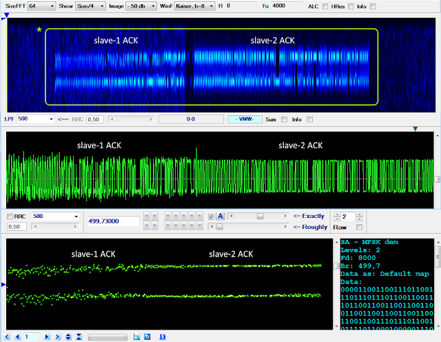
Fig. 8

Due to the partial collisions, the shorter ‘ACKs’ as expected only exhibits part of the preamble sequence (figure 9):

Fig. 9
 
The hypothesis of overlapping modems is also supported by the examination of the SNRs of the two signals, as shown in figure 10 (thanks to "Audacity" free software [1]).
 
Fig. 10
 

Differential demodulation in chronological order of the recorded ‘ACKs’, does not offer much additional information other than a very varied 48-bit format (see figure 11). In the figure the lengths of the data sections are unequal. That format is due to the fact, that I somewhat arbitrarily used the beginning of the trailing bit reversal ("01") sequence (if any) as a delimiter; there is no obvious evidence of parity bits nor of particular patterns. Bit reversals and preambles have been removed.


So, judging from the observations described above, it seems that we are facing a more complex scenario than the simple two nodes in half-duplex, ie a network consisting of multiple (at least three) stations that exchange messages in ARQ mode, sometimes one sender and two correspondents at time, and sometimes just one correspondent.

With a cautious approach, I could imagine three reasons for the collisions:
a) They might be due to the fact that the correspondents sometimes are unable to hear each other and thus 'think' that it's their turn to transmit. However, one would expect a network with a master station broadcasting and several slave outstations responding to have a centrally determined schedule with fixed intervals preventing outstations from interfering with each other, somewhat like Link-11, or, even better, a GPS-synched network like STANAG-4538

b) It is also possible that the reason for these phenomena are seen as collisions are due to the location of the intercepting station in relation to the location of the network stations being monitored, which could give rise to differences in the propagation time at the interception site and the intended recipient

c) And, finally, the short ‘ACKs’ might be a combination of acknowledgement and request to transmit or changeover commands ('you next')
 
Further investigations are in progress... and thanks to my friend Nicola for the editing.

15 December 2021

Chinese PSK2 2400Bd serial waveform

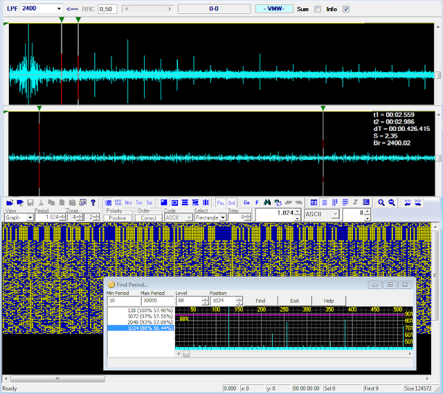
This is my follow-up to an interesting post discussed on the radioscanner.ru forum about a PSK2 transmission of the Chinese Navy and started by my friend KarapuZ [1].  The raw demodulated stream consists of an initial preamble followed by data block consisting of a serie of 16-bit structures which are delimited by solid columns of "1"s or "0"s; the  period is calculated in 3072, 2048, and 1024 bit (128-bit length is due to the preamble sequences): the percentage values in figure 1 indicate respectively  the average ACF value for the given period, followed by the real value of the ACF for that period). Although the value of 1024 bit is the third positive result, both ACF and CCF indicate this as the most likely, being the other two integer multiples of it (x3, x2): this way, the stream consists of 64 "channels", each consisting of 16 bit.

Fig. 1

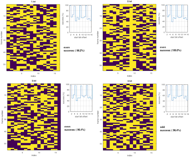
As noted by my friend Cryptomaster, the 15-bit information between the solid columns is parity-checked; thus, assuming the parity bit is added, as usual, after the data string, each row could consist of 14 bits for data (x) + 1 parity bit (p) + 1 delimiter bit (d): xxxxxxxxxxxxxxpd.
 
I proceeded to the parity check of some channels taking into account all sixteen bits, given that: 
 
* the add of a column of "0"s does not affect the parity checksum of the channel (even or odd); 
* the add of a column of "1"s switches the parity checksum (from even to odd and vice-versa).

The results for some channels are shown in figure 2, it's to be noticed that the max number of dd/even parity parity matches occurs after shifted the stream (offset >1). Looking at the sequence of the parity checksums of the examined channels, and considering the previous assumptions, we get an apparently random alternation of odd and even parity checksums. 

Fig. 2

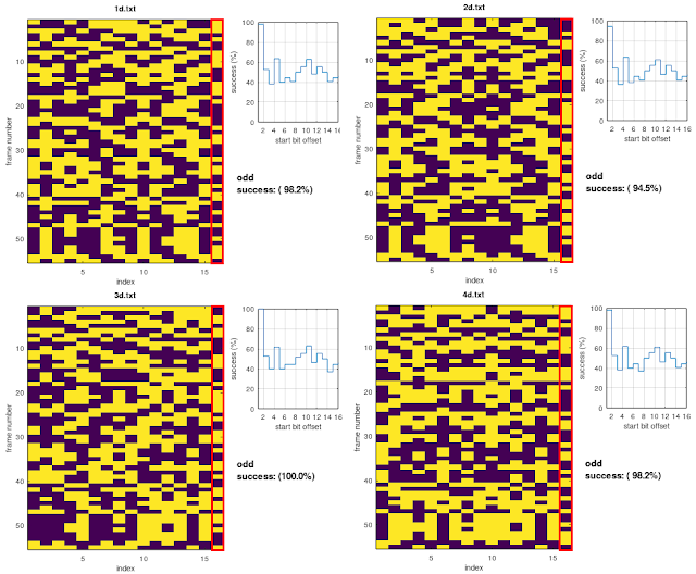
After the differential decoding, the channels' "delimiters" disappear, so I tried to get the differential decoding of each channel resorting to some sort of workaround: basically I cut off the 16-bit channels from the plain decoding and then I differential decoded each of them. Yes I know, it's an hazard as it assumes that the channels are individually differential encoded (in real-world the first bit of the n channel depends on the last bit of the n-1 channel) ... however, in that way, the channels are all odd-parity checked and perfectly aligned (figure 3).

Fig. 3 - channels after their individual differential decoding

Since the use of a single parity bit cannot correct any errors, and given the amount of data transmitted, my idea is that they could use a kind of (16,k) coding with the overall parity bit added at the end of the codeword.

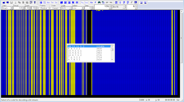
For what concerns the preamble sequence, it can be successfully descrambled using the polynomial x^18+x^13+x^11+x^5+x^2+1 (figure 4): it means that the preamble actually consists of a 128-bit pseudo-random sequence (PRBS) which is part of the M-sequence generated by the aforedmentioned polynomial.

Fig. 4 - 128-bit PRBS used as preamble

https://disk.yandex.com/d/b8oQdmhTJcJhPg

[1] http://www.radioscanner.ru/forum/topic40144-14.html#msg1540957 

6 August 2021

another approach to the analysis of unresolved sync sequences

The pseudo-random binary sequences (PRBS, also referred to as pseudo-random bit sequences) are largely used in telecommunication (data scrambling, sync sequences, field delimiter markers, jamming, stream ciphers, bit-error rate tests, ...) and are usually generated by physical Linear Feedback Shift Registers (LFSRs), or their software implementations. Sometimes it may happen to come across sync sequences or particular patterns of which it is not possible to trace back to the generator polynomial and therefore to the structure of the used LFSR. This happens because most of the time PRBS are drained from the serial output of the LFSR and therefore the search for the generator polynomial takes place brute-force and "directly" on the pattern being analyzed. 

Fig. 1 - x^4+x^3+1 LFSR with serial output

But it could happen that the pseudo-random sequence is instead formed by taking the outputs (the states) of all the stages that compose the LFSR, let's say a parallel-output PRBS as an alternative counterpart to the serial-output one.  

Fig. 2 - x^4+x^3+1 LFSR with parallel outputs

In the first case (serial-output PRBS) the sequence has a length (or period T) of 15 bit while in the second case (parallel-output PRBS) the sequence has a period  of 15×4=60 bit length. Analyzing the latter as if it were a serial-output one could produce not significant or even misleading results, as shown in figure 3.

Fig. 3 - results after analyzing the serial and parallel output of the same LFSR (x^4+x^3+1)

What we need is establish the number of stages that compose the unknown LFSR, after which a single stage can be isolated and its (serial) output sequence analyzed. Well, assuming T is the period of the pattern, this one shall be reshaped to a c-columns array where c = T/((2^n)-1), where n = (2,3,4,5,6,7...).  After reshaped the original pattern, the search for the generator polynomial can be performed on any of the c columns of that array.  In a few words, we have to found the valor the period T in table below (if any) and then reshape the pattern according to the corrispondent value of c (ie, the number of the stages of the LFSR):

In case of the x^4+x^3+1 LFSR mentioned above, its parallel output has a period length of 60 bit and  is divisible by 15, giving 4 as the number of the stages: the polynomial is then easily verified after reshaping the 60-bit pattern to a 4-bit array (figure 4). Notice that the the length of the serial-output PRBS is just equal to 15.

Fig. 4

Other examples are shown below:

Obviously, the above is valid only for certain lengths of the period T and it is not certain that it is also valid for generator polynomials that are not primitive, i.e. they do not generate sequences of maximum length [1]. Moreover, it could be argued that a multiplexer is needed to send the parallel-output PRBS, but the whole sequence could also be stored and then pre-loaded and added to the bitstream as many times as needed, or it could happen that only a segment of a parallel-output PRBS could be used.

I am definitely not a "mathematician" but I think that sometimes the above method, though a bit raw, can be useful to unearth the LFSR which is hidden behind particular sequences.

[1] https://i56578-swl.blogspot.com/p/polynomials.html

3 August 2021

use PuTTY as Arduino monitor for LFSR circuits

Given the lack of really interesting signals on air, at least these days or no luck in hunting, I am playing with the semi-hardware (1) implementation of pseudo-random sequence generators: a way to spend these hot afternoons combining electronics and signal analysis. Waiting for the delivery of the 74xx595 chips, necessary for the 188-110A sequence generator, I wanted to implement a version of the LFSR (Linear Feedback Shift Register) described by the polynomial x^4+x+1 and verify - even if there was no need - its binary sequence. 

So, why a post title about PuTTY? I needed to save the bit stream produced by the circuit for its subsequent graphical representation but unfortunately the Arduino' console (embedded in its development environment) does not allow the content to be saved unless you stop the process and use the copy & paste method, a workaround not always effective in case of output that cause scrolling screen: using PuTTy is just what you need. "Putty" is a free SSH and telnet client for Windows and if it's not yet part of your resources you can quickly download and install it from its site [1]. After launched, select the right serial port number and speed as indicated by Arduino then on the session tab select the printable output and the path of the output file (figure 1): that's all, power-on your circuit and connect Putty, you do not have to run the Arduino environment to get a monitor.

Fig. 1 - configuring PuTTY for use as Arduino' monitor

Fig. 2 - PuTTY at work

Back to the LFSR circuit (four D-type Flip Flop and one XOR gate), its logic is quite simple and does not require much explanation even if I'm not really an artist in wiring the bredboards (figs. 3,4). Just notice that I use the Arduino MEGA 2560 so if you do not use such board you will have to change the input/output pins 6 (preset/clear), 8 (clock), 10 (Q1), 11 (Q2), 12 (Q3), 13 (Q4) by editing the sketch [2] according to your choices. Mind you that the clocking speed is exaggeratedly low to allow both the set of  the initial state of the registers (see below) and an easier reading of the monitor.

Fig. 3

Fig. 4

As said, the LFSR is described by the primitive polynomial x^4+x+1, i.e. its sequence is termed as m-sequence (maximum-length sequence) and has a length T = 2^n -1, where n is the number of the used registers (also termed as "stages"); in this case the LFSR employes four registers thus produces a 15-bit length sequence that repeats itself over time. Storing the "state" of each register (outputs Q1, Q2, Q3, Q4) we get 4 × 15 = 60-bit length pattern (figure 6).
Notice that the 0000 state is never crossed since in that state the sequence simply does not start, the registers are as stuck in that state; therefore, the 0000 state is never used as initial state (or "seed") of the LFSR. To start the state' cycles and set the seed to 1000, you will need to keep pin2 HIGH just for a clock positive transition, ie simply wire pin 2 - the data input of the first register - to the +5 V line of the bredboard, clock pulses are monitored by the LED in figure 4. 

Obviously, the same sequence will be obtained by simulating the LFSR using an Octave script (LFSRv2.m) [3] or the Logic Simulator App [4] [5] or the LFSR Testbench too [6]: you have many tools at your disposal.

Fig. 5 - LFSR states output logged by PuTTY and states output produced by Octave script

Fig. 6 - the 60-bit patterns generated by the four states of the LFSR

The sequences in figures 5-6 are obtained implementing the "many-to-one" feedback structure but you could also implement its "one-to-many" counterpart (2): in which case the sequence of the states will be slightly different (!) though the initial states are the same (figure 7).

Fig. 7 - many-to-one and one-to-many feedback structures for x^4+x+1 LFSR

«A way to spend these hot afternoons combining electronics and signal analysis» I said... yep, but the beach is much more better! 

(1) semi-hardware since some features such as the clock are software implemented 

(2) in "one-to-many" configuration there is never more than one level of combinational logic in the feedback path, irrespective of the number of taps being employed in the traditional "many-to-one" configuration (increasing the levels of logic in the combinational feedback path can negatively impact the maximum clocking frequency).

[1] https://www.putty.org
[2] https://disk.yandex.com/d/U4rXrZ7JWWgAGQ
[3] LFSRv2.m Octave script https://disk.yandex.com/d/jOX64f8u19jYFw
[4] Logic Simulator project https://disk.yandex.com/d/UcLU_1eAwtubXA
[5] Logic Simulator Apk https://logic-circuit-simulator-pro.it.aptoide.com/app
[6] https://disk.yandex.com/d/hMe696WAWjth8Q


26 July 2021

playing with Arduino and a 12-bit LFSR


The circuit is just a test of the operation of the 12-bit LFSR x^12+x^6+x^4+x+1 used in 188-110A serial tone modems, in view of its full implementation; its software simulation has already been seen in a previous post, to which I refer for further insights. The 12 flip-flops and the 3 XOR gates implement the "one-to-many" configuration, according to the 188-110A standard. Since the 74xx374 does not provide the asynchronous preset / clear inputs, the LFSR is a "free runner" that is, it is not reset to a certain initial state (seed) after n-cycles; therefore all the circuits related to loading the initial pattern (0xBAD) are missing. 

Pinning and logic circuit (connections) are shown in figure 2: the electric connections (+/- 5V power) are omitted, the connections to the pins of the Arduino board are indicated (notice I used AT MEGA 2560 board so you had to change connections and code in case you use a different board).

Fig. 2 - logic connections and pinning

The 220 ohm resistor & the blue led visible in the photo on the clock line, are not reported in the circuit, they just show the clock pulses... obviously in case of a very low clock speed.

The code of the sketch is quite simple, I just used a random number generator to simulate symbols 0-7 from Modified-Gray Decoder (MGD) and a 8x8 array to perform the scrambler: the tribit number supplied from the random number generator is modulo 8 added (mod8[LFSRsymbol][randSymb]) to the three bit value supplied by LFSR (pins 53,51,49). Results are written into a buffer which is then sent to the serial port (figure 3).

Fig. 3


The 74HC374 is an octal positive-edge triggered D-type flip-flop with 3-state outputs (the second 74HC374 is half used, ie it provides only 4 flip-flops). The device features a clock (CP) and output enable (OE) inputs. The flip-flops will store the state of their inndividual D-inputs that meet the setup on the LOW-to-HIGH clock transition. A HIGH level on OE causes the outputs to assume a high impedance OFF state (OE input does not affect the state of the flip-flops). The74HC86 is a quad 2-input EXCLUSIVE-OR gate used to form the feedback chain.

https://disk.yandex.com/d/7gestYtENRF6VQ

3 May 2021

unid, and somewhat peculiar, 1200Bd BPSK

Cleaning up one of my hard disks I came across an old recording (year 2014) that had no comment file associated with it, so I decided to take a look at it and see what exactly it was. The recording consists of different length bursts, each burst is modulated with PSK2 at a symbol rate of 1200Bd: nothing particularly interesting unless its ACF and, consequently, its period. Indeed, the ACF results in 373.74 ms (Figure 1) that make a length of the period of 448.5 bit (PSK2 @1200Bd), but after the differential decoding the bitstream shows a 897 bit length period, ie just the double of the value obtained using the phase detector. 

Fig. 1 - 373.74ms ACF corresponding to a 448.5 bit length period

As you know, a such situation is typical in asynchronous framings that have the stop-bit of 1.5 or 2.5 in length: for example, in case of a 5N1.5 framing the bit editor groups two 7.5 bit frames into a single 15 bit pattern because it can't represents a length of half bit. That's just what may happen here: the bit editor reshapes the bistream to a 897 bit length period and draws two frames (Figure 2) consisting of two 100 bit sync sequence, each followed by a data block.

Fig. 2 - 897 bit period

However, it's to notice in Figure 2 that the lengths of the two data blocks are different (348 and 349 bit) while the sync sequences have a constant length of 100 bit. Looking at Figure 3, the synchronization patterns are left and right inclined for periods of length 488 and 489 bits respectively: that behavior may confirm the 448.5 bit frame as measured above.

Fig. 3 - inclined 100 bit patterns in 448 and 449 bit framings

Talking about it with my friend cryptomaster, we agreed two possible hypothesis:

1) the length of the frame is 897 bit: the framing consists of  two 100 bit sync sequences that are interspersed with two data blocks of  348 and 349 bit; the variable length of the two data blocks and the two sync patterns are a proper feature of this waveform;

2) the length of the frame is 448.5 bit: the framing consists of 100.5 bit for the sync sequence (possible, even if unlikely) followed by 348 bit for the data block.

In order to verify the second assumption,  I set the speed of the PSK demodulator to a double value (2400Bd) so to emerge the missing half bit, if any. The resulting bitstream is shown in Figure 4: the period has the expected length of 1794 bit (2 × 897) and it's possible to see sync sequence patterns of 201 bit in length, ie just the extra bit that was missing.


Fig. 4 - 201 bit sequences in the bitstream @2400Bd

Indeed, the 1794 bit period is arranged as: | 201 bit sync  | 696 bit data | 201 bit sync | 696 bit data |;  since the speed of demodulation is doubled, dividing by 2 we get a 448.5 bit frame consisting of 100.5 bit for the sync sequence followed by 348 bit for data:
 

However, keep in mind that the above bitstream was achieved after a forcing of the demodulation speed to 2400Bd (instead of the effective 1200Bd) and the subsequent differential demodulation: more observations are needed to confirm the 100.5 bit length of the sync sequence.
By the way, the 100 bit sequence may be de-scrambled by the polynomial x^7+x^4+1. Looking for a scrambler polynomial in the 201-bit sequence does not make sense since the way it was obtained.
 
Fig. 5 - x^7+x^4+1 polynomial

Back to the signal, it's interesting to note that some burts have a ~230ms preamble consisting of 8 x PSK2 1200Bd "pulse" (Figure 6): I don't know the reasons and what it can depend on, signal strength and fading seem to indicate that it is not an exchange of messages between two nodes or an ARQ mode.

Fig. 6

 https://disk.yandex.com/d/SIqbhycJkrLjAg

12 March 2021

Rus PSK4 1200Bd: solved

The questions related to the "nature" of the 1022-bit period of the QPSK 1200Bd signal (see the previous post) has been solved thanks to the help of my friend cryptomaster: I was waiting for traffic ("I tuned it waiting for traffic, but luckless until it went off") but actually it was already there!
He had the great intuition to reshape the bitstream into di-bit symbols, ie 2 bits per row given the 4ary modulation, then we gone on analyze the two columns separately and found the m-sequence x^9+x^5+1 (or the equivalent x^9+x^4+1) in the second column: therefore, each bit of data is followed by one bit of the m-sequence, ie the 1022-bit period consists of 511 bit of data interleaved with the 511 bit of the sequence generated by the LFSR x^9+x^5+1 (Figure 1).

Fig. 1 - x^9+x^5+1 sequence in the 2nd column
 
The next step was to see if the same polynomial is to some extent involved in the bits of the first column. Based on the ninth degree of the polynomial x^9+x^5+1, a 9x511 parity check matrix was constructed, assuming that an H(511,502) code - based on that same polynomial - is used in the fomation of the bits of column #1. Notice that  a H(m,k) code is a Hamming code that encodes k bits of data into m bits (the codeword), adding m-k parity bits (CRC). 
Our parity matrix consists of a 9x502 check sub-matrix and a 9x9 identity sub-matrix (Figure 2):
 
Fig. 2 - Hamming parity check (511,502) matrix

As you know, the CRC formation is carried out by comparing column-by-column the k bits of each data row in turn with all the (m-k) rows of the check sub-matrix and counting the "vertical" correspondences of the "1"s of the data row and the r-row of the check sub-matix: if the count is odd then the CRC bit #r will be set to "1", otherwhise will be set to "0". That way, the (m-k) bits of the CRC is appended to the k bits of the data row just examined and the computation go ahead with the next data row.
That said, the bitstream of column #1 (the file demod-bit1.txt) has been reshaped to form a 511-column matrix of codewords. Manually checking the about two hundred 511-bit length codewords would have been a nightmare, so I wrote a short Octave script that would do the job for me and calculate the 9-bit CRC of each row along with a simulation of the final PSK4 modulation - the result in Figure 3.
 

Fig. 3 - 9 bit CRC rows (left); PSK4 modulation of data +CRC (right)

By comparing the calculated CRC bits (Figure 3 on the left) with the bit stream of column n. 1 (Figure 4), it is clear that each row of the bitstream is nothing more than a "codeword" consisting of 502 bits for data plus 9 bits for Hamming CRC, ie the 511-bit period that we saw.

Fig. 4 - the bistream of column #1

My friend cryptomaster tested also a 2016 recording and found it matches with the above conclusions (Figure 5). For what concerns the nature of the 502-bit strings of data they are probably telecontrols, further recordings are need. A possible (!) functional block diagram of the modulator is shown in Figure 6.
 
Fig. 5
 

22 December 2020

An odd STANAG-4481F link

Odd STANAG-4481F transmissions consisting of (apparently) continuous KG-84/KIV-7 64-bit sync sequence, spotted on 11222.0 Khz (CF): this is the first stime I hear S-4481F on that frequency. These transmissions have been going on h24 for days and always keeping the same modality.

Fig. 1 - note the oscillations during the mark-space switch

As pointed out by my friend cryptomaster, although k500 decoder recognizes the KG-84 64-bit sync sequence, actually the stream consists of the 63-bit m-sequence generated by the polynomial x^6+x^5+1, or its counterpart x^6+x+1 (Figure 2); this way, the KG-84 sync sequence is obtained by adding one "1" bit. Otherwise, the KG-84 sync sequence may be obtained assuming (as the decoder does) the last bit "1" of the sequence n as the first bit of the sequence n+1, i.e. as if that bit were "in common" bewteen two consecutive sequences (Figure 3). In a few words, decoders are tricked by that 63-bit sequence.
In my opinion, the choice to send that m-sequence is not a "casual" one - they could have used any other test pattern - but raher it's a deliberate choice since its closeness to the KG-84 sync sequence (just one bit) and the fact that KG-84 is largely used in S-4481F links. Interestingly, the stream resulting after the removal of the scrambler consists of  bits all set to "1"; as above, they could have used any other scrambler polynomial.
 
Fig. 2
Fig. 3
 
Fig. 4 - a STANAG-4481F decoder working the 11222.0 KHz transmission

It's difficult to say what it is exactly: maybe tests in view of the setup of a new link,  a frequency marker or maybe some trials. Every attempt to find the Tx site by using TDoA method is different, almost surely it's somewhere in the North-East of US, most likely NSS/AFA Davidsonville (Figure 5).
I will update the post as soon as something new comes out. 
 
Fig. 5a - according to these DF attempts, TX seems located north of Baltimore (likely Davidsonville)
Fig. 5b - other TDoA attempt obtained by selecting receivers from east to west (...still Davidsonville)