Showing posts with label Comments. Show all posts

24 June 2026

DTE-DCE Handshaking and Transmission Management

Following my previous post, a colleague reached out asking for clarification on the real-world, non-simulated operations of Data Terminal Equipment (DTE, typically a host PC) and Data Circuit-terminating Equipment (DCE, the HF modem). This inspired this post, which consolidates and structures the technical information scattered across the web. To ground these concepts in a practical scenario, this analysis focuses on an SDTE — more formally specified in NATO documentation as the SIS-DTE (Subnetwork Interface Service Data Terminal Equipment) — executing the STANAG 5066 stack. For clarity and consistency, this component will be referred to simply as the DTE throughout the remainder of this post.

Operating high-speed data networks over the High Frequency (HF) ionospheric channel presents an exceptional engineering challenge. The channel is inherently non-stationary, susceptible to severe multipath fading, atmospheric noise, and Doppler shifts. To maintain physical-layer synchronization under these hostile conditions, tactical waveforms such as MIL-STD-188-110A and NATO STANAG 4285 decouple the physical modulation speed from the actual user throughput.
Regardless of the data rate selected by upper-layer protocols, the physical over-the-air modulation speed remains strictly locked at 2400 baud (symbols per second). Scaling the data rate down from 2400 bps to a ruggedized 75 bps is achieved not by slowing down the radio's RF emission engine, but by dynamically increasing the density of Forward Error Correction (FEC) codes, interleaver settings, and bit-repetition factors. Managing this asymmetry requires an explicit structural division between session logic and physical timing. This post outlines the interface architecture, the real-world transactional flow, the critical impact of interleaver latency, and the modern IP-based evolution of systems operating between a STANAG 5066 DTE server and a DCE tactical radio modem.

1. Deconstructing the Interface: Baud, Bits, and Protocol Overhead
A frequent point of confusion in tactical data link design is the relationship between the over-the-air symbol rate (baud) and the baseband clock frequency driven across the physical DTE/DCE interface.

1.1. The 8-PSK Modulation Reality
In a standard MIL-STD-188-110A single-tone waveform, the modem operates at 2400 baud using 8-Phase Shift Keying (8-PSK). Because each symbol represents one of eight distinct phase states, it encodes exactly 3 bits of raw information (23=8). This establishes a constant over-the-air aggregate physical line rate of: 2400 baud × 3 bits/symbol = 7200 bps

1.2. Waveform Geometry vs. Coding Overhead
By subtracting the useful user payload from this 7200 bps aggregate line rate, we can isolate the exact volume of protocol overhead. However, this overhead is not strictly composed of Forward Error Correction (FEC). In military standard waveforms, a significant portion of this bandwidth is consumed by waveform geometry—specifically, channel-probing blocks.
The waveform structure alternates strictly between blocks of unknown data symbols and blocks of known pseudo-random training patterns (e.g., 20 data symbols followed by 16 probe symbols). The receiving Digital Signal Processor (DSP) uses these known probes to continuously map and counteract ionospheric fading and multipath distortion.

- At the maximum user rate (2400 bps):
7200 bps (Total Rate)−2400 bps (User Payload)=4800 bps (Overhead)
In this high-clearance scenario, the modem dedicates exactly 66.67% of its total over-the-air bandwidth to the combination of FEC data packing and synchronization probes to stabilize the link.
- At a highly ruggedized sub-rate (150 bps):
7200 bps (Total Rate)−150 bps (User Payload)=7050 bps (Overhead)
When channel conditions deteriorate, the protocol overhead consumes 97.92% of the total bandwidth. This mathematically demonstrates how aggressively the physical layer wraps each individual user bit in an extensive repetition and convolutional coding matrix to survive extreme signal degradation.

1.3. The Shift in Timing Leadership
To prevent buffer underrun or overflow during these speed adjustments, the system splits leadership between two distinct control domains:
- The DTE (STANAG 5066 Server) rules Session Configuration: It evaluates link performance via Automated Repeat Request (ARQ) frame error rates and dictates what data rate and interleaver depth must be utilized via its Dynamic Rate Adaptation (DRA) algorithms.
- The DCE (Modem) rules Physical Timing: Once a rate is selected, the modem operates as the master metronome. 

In a legacy synchronous interface—such as RS-530 or MIL-STD-188-114—the modem physically scales its baseband clock output (TX_CLK) to match the active user bit rate. If STANAG 5066 commands a 150 bps rate, the modem's internal oscillators drop the physical hardware line clock on the data cable to exactly 150 Hz. The DTE functions as a slave to this clock, forcing its internal serial shift registers to march precisely to the physical rhythm driven by the DCE.

2. Legacy Chassis Topology: Separating the Data and Control Planes
Using a legacy, rack-mounted standalone tactical modem—such as the Harris RF-5710A—as an architectural reference, the physical implementation mandates two completely independent cabling pathways to separate synchronous data delivery from runtime reconfiguration.


2.1.The J3 Remote Control Port (The Control Plane)
The J3 interface is an asynchronous serial port (typically configured as standard RS-232). It handles no user payload data. Instead, the STANAG 5066 subnetwork layer uses this link exclusively to transmit out-of-band management commands directly to the modem's central processor. These commands are formatted using either proprietary command architectures or standardized STANAG 5066 Annex E modem control strings.

2.2. The J2 Data Port (The Data Plane)
The J2 interface is a high-speed synchronous serial interface configured for RS-530 or MIL-STD-188-114 balanced signaling. It contains the physical baseband data lines (TX_DATA, RX_DATA), the master hardware clocks driven by the modem (TX_CLK, RX_CLK), and the discrete hardware flow control lines: Request to Send (RTS) and Clear to Send (CTS).

3. The Real-World End-to-End Transaction Flow
When an application connected to a STANAG 5066 server attempts to transmit a data block across an adaptive HF link, the interaction across the J3 control plane and the J2 data plane executes a precise sequence.
 
Step 1: Link Adaptation Assessment
The STANAG 5066 subnetwork layer processes incoming link-quality statistics from the distant receiving station. Noting a drop in the Signal-to-Noise Ratio (SNR), the DTE's Dynamic Rate Adaptation algorithm calculates that the link must drop from 2400 bps to 150 bps with a Long Interleaver setting to penetrate local atmospheric noise.

Step 2: Out-of-Band Reconfiguration (J3 Interface)
Before asserting any data lines, the STANAG 5066 server constructs a management frame enclosing Annex E configuration strings, e.g.:
[DTE -> J3 Async Input]: Command -> Set Waveform: 110A_SINGLE_TONE; Rate: 150; Interleaver: LONG;

 
The internal controller of the Harris RF-5710A parses the asynchronous packet, reconfigures its internal DSP algorithms, and prepares the physical layer to alter its baseband clock distribution.

Step 3: Interface Clock Realignment (J2 Interface)
The modem immediately scales its physical hardware clock synthesizer engine down. The physical TX_CLK line output on the J2 serial connector drops from a 2400 Hz square wave down to a steady 150 Hz pulse train. The hardware interface is now locked into the correct physical sub-rate window.

Step 4: The Physical Transmission Handshake
With the interface speed stabilized at 150 bps, the synchronous data transfer proceeds:
- DTE Asserts RTS: The STANAG 5066 server drives the physical RTS line on the J2 connector LOW (Active State). This serves as a direct hardware interrupt instructing the modem to key the attached HF radio transmitter.
- The Transmitter Keying and Preamble Phase: The modem keys the radio transmitter. It keeps the physical TX_CLK signal silent and the CTS line de-asserted. During this turnaround window, the modem generates and broadcasts a physical-layer over-the-air synchronization preamble. This known tone pattern allows the distant station’s receiver to achieve phase lock and evaluate interleaver synchronization.
- Modem Asserts CTS: Once the over-the-air preamble transmission concludes, the DCE drops the physical CTS line on the J2 connector LOW. Simultaneously, it activates the 150 Hz synchronous TX_CLK line.
- Synchronous Bit Burst: The STANAG 5066 DTE detects the active CTS boundary. On every rising edge of the incoming 150 Hz clock pulse provided by the modem, the DTE shifts one bit of data onto the TX_DATA wire. The modem samples this data precisely on the subsequent falling edge, funneling it directly into the DSP's FEC packing matrix.

4. The Interleaver Latency Penalty: The Hidden Operational Constraint
A critical operational factor that engineers must account for when deploying STANAG 5066 protocols over sub-rates is interleaver latency.
To protect data from long, continuous bursts of noise (fade duration), the modem utilizes a block or convolutional interleaver matrix. The transmitter rearranges the chronological order of bits over a specific time window before sending them over the air. The worse the channel conditions, the larger the interleaver matrix required.
When dropping to a sub-rate like 150 bps with a Long Interleaver, this matrix introduces severe physical delivery delays:
- The Buffering Constraint: The transmitter's DSP must wait until enough bits have accumulated to completely fill the structural interleaver matrix before it can shuffle them and begin actual over-the-air transmission.
- The Latency Cost: At 150 bps, filling a Long Interleaver matrix introduces a processing latency of 4.8 seconds or more at the transmitter, and another 4.8 seconds for de-interleaving at the receiver.
Consequently, the first bit of the user payload does not emerge from the receiving station's modem until nearly 10 seconds after the DTE begins shifting data. This structural delay dictates that the STANAG 5066 layer must scale its internal Automated Repeat Request (ARQ) frame timers aggressively. If the software's acknowledgment timeout timers are set too short, the DTE will prematurely assume a packet was dropped and retransmit it, clogging the narrow 150 Hz pipeline with duplicate traffic.

5. The Modern Evolution: Transitioning to IP-Based Software Defined Radios
The legacy Harris RF-5710A represents a 'High-Data-Rate, IP-Ready, and Annex-E Compliant' evolution capable of driving the HF channel up to 9600/12800 bps via adaptive QAM, enabling the efficient utilization of modern STANAG 5066 servers featuring Dynamic Rate Adaptation (DRA). It serves as the ultimate historical bridge between old-world balanced cabled engineering and modern consolidated networking architectures.
In contemporary Software Defined Radios (SDRs)—such as the Harris Falcon III series—the separate physical modem and transceiver chassis collapse into a single integrated unit. Physical J2 and J3 serial connectors are completely replaced by a single Ethernet interface running standard IP stacks. This shifts the implementation from hardware-level pinning to software-defined protocol boundaries:
- The Control Plane is virtualized. Instead of serial strings sent over a dedicated RS-232 line, the STANAG 5066 node establishes a TCP/IP or UDP socket connection to a designated management port on the radio, sending configuration packets using modernized subnetwork control protocols (such as the HF Radio Control Protocol / HRCP).
- The Data Plane eliminates physical clock lines (TX_CLK). The Data Plane eliminates physical clock lines (TX_CLK). Baseband streaming bits are packaged into standardized encapsulation networks, such as STANAG 4538 or virtual synchronous serial profiles over IP. The radio's internal software clocks handle the synchronization between incoming IP packets and the underlying DSP modulator frame boundaries.

Despite this transition to IP-routed pipelines, the core architectural logic remains completely unchanged. The STANAG 5066 software node remains the logical king of data rate selection based on link performance, while the radio's internal DSP remains the absolute metronome of physical over-the-air ionospheric synchronization.


20 March 2026

BPSK/QPSK Phase Ambiguity and Bit-Shift

Dealing with phase ambiguity and bit shifting in a demodulated BPSK/QPSK bistream are two of the most common obstacles that prevent you from actually understanding what the transmitter sent.

1. BPSK Phase Ambiguity ("Is it Inverted?")
In BPSK, data are represnted by shifting the phase of a carrier wave: 0° might represent a binary '0' 180° might represent a binary '1'.
The problem arises during carrier recovery. The receiver modem has to generate a local reference carrier to demodulate the signal. However,  an "universal" PSK demodulator - as the one of SA Signals Analyzer - cannot distinguish between a carrier at θ and a carrier at θ+180°. The Result: if the demodulator locks onto the phase 180° out of sync, your data gets inverted. Every '1' becomes a '0' and every '0' becomes a '1' (Figure 1). Without a reference, the demodulator has no way of knowing it's reading the entire stream upside down.

Figure 1: Outputs of the "universal" SA PSK demodulator processing the same BPSK signal.

2. The Bit-Shift Problem ("Where does it start?")
Bit-shifting (or timing offset) occurs when the modem's clock isn't perfectly aligned with the incoming symbols. The Cause: even if your frequency is correct, if your "sampling instant" is off, you might sample the signal during a transition between two bits. The Result: this leads to Intersymbol Interference (ISI). I If the shift is bad enough (e.g., a half-symbol shift), the receiver might slip a bit entirely, causing the rest of the data stream to be misaligned with the intended word boundaries (frame synchronization). For istance, if you see 0x33 or 0x66 rather then an expected Sync 0xCC sequence, you might be inverted, or you might just be 2 bits off in your alignment (Table I).

Table I : bit-shift effects
3. How it's fixed by the sender
3.1. Known Sequences (Preamble, Framing Sequences, Pilot/Training Sequences)
Sending a known pattern (e.g., 111101011) at the start of a packet, i.e., a general packet framing (e.g., File headers). For Phase: If the receiver sees the inverse of the preamble, it knows to flip all subsequent bits. For Bit-Shift: The preamble allows the receiver to find the exact "start" of the message, aligning the clock and preventing bit-shifts.
 
3.2. Unique Word (UW) / Synchronization Marker
By periodically inserting a known "Unique Word" (UW), often called Synch Marker or Synch Word, the receiver can constantly check if it's still aligned. If it finds the UW shifted by one position, it shifts its internal buffer to compensate.

3.2.1. Solving Phase Ambiguity with UW
If the receiver is locked 180∘ out of phase, the entire incoming stream is inverted. The receiver looks for the UW (e.g., 011010): if it finds 011010, it knows the phase is correct. If it finds 100101 (the exact inverse), it knows it is 180∘ out of phase. The receiver simply flips every bit in the payload following that inverted UW.

3.2.2. Solving Bit-Shifts with UW
Because the receiver is constantly sampling, it doesn't initially know where "Bit 1" of a frame begins. It just sees a continuous stream of bits. The receiver runs a Cross-Correlation. It slides its "known" UW over the incoming bitstream one bit at a time. When the correlation peak hits its maximum, the receiver has found the exact alignment. It "snaps" its frame buffer to that position. Any bits received before that peak are discarded as noise or previous frame leakage; everything after is the valid payload.
Why not just use the Preamble?
The Preamble (usually alternating 101010) is great for helping the hardware clock "lock on" to the speed of the data, but it’s terrible for alignment because every shift looks the same. The Unique Word is designed to be mathematically "un-ambiguous", it has a sharp autocorrelation peak so the receiver knows exactly which bit is the first bit.

3.2.3 A note about Barker Codes
Barker Codes are the most popular choice for a Unique Word (UW) because they are mathematically optimized to be "self-distinguishable." While any random sequence could technically be a UW, Barker codes are used because they minimize False Positives. If you used a sequence like 1111, the receiver might think it found the start of the frame four different times as the bits slide by. With a Barker code, there is only one clear answer.
In Table II shows the list of the known Binary Barker Codes in a plain text ASCII format.In this representation, a '1' corresponds to +1 (no phase shift) and a '0' corresponds to −1 (180∘ phase shift) in a BPSK system.
Table II: known Binary Barker Codes

3.3. Differential Encoding (DBPSK)
Instead of mapping bits to absolute phases, the source modem map them to changes in phase:
0: Stay the same phase as the last bit.
1: Flip the phase 180° from the last bit.
Even if the receiver is 180° out of phase, the difference between bits remains the same, effectively killing the phase ambiguity problem.
 
3.3.1. Solving Phase Ambiguity with Differential decoding
Instead of searching for a Unique Word to see if the bits are inverted, we change how data are encoded so that an inversion doesn't actually matter: in Differential BPSK (DBPSK), we a bit is mapped to a change in phase.

3.3.2. Solving Bit-Shifts with Differential decoding
Differential decoding does not solve bit-shifts on its own. While it is a "magic bullet" for Phase Ambiguity, it is actually quite vulnerable to Bit-Shifts. Differential decoding works by comparing the current symbol (Sk​) to the previous symbol (Sk−1​). If the receiver has a bit-shift (timing offset), it means the "window" where it samples the sine wave is shifted. Instead of capturing a clean 0° or 180° symbol, it might sample right on the edge where one bit ends and the next begins.
If the receiver is "off by one bit," the differential decoder will compare:
- Bit 2 to Bit 1 (instead of Bit 1 to Bit 0)
- Bit 3 to Bit 2 (instead of Bit 2 to Bit 1)
The math still "works" (no phase inversion), but your entire data stream is now offset. If you were expecting a 16-bit sensor reading, you now have the last 15 bits of that reading plus the first bit of the next one. The data is mathematically "correct" but contextually "garbage."
 
4. QPSK modulation
When we move from BPSK (2 phases) to QPSK (4 phases) the complexity of phase ambiguity and bit-shifting increases significantly. If your Bit-Shift is off by just one bit in a QPSK system, you aren't just starting the message late; you are splitting the symbols in half:
Correct Alignment: [BitA BitB] [BitC BitD] → Symbols read correctly.
1-Bit Shift: BitA [BitB BitC] [BitD BitE] → Every single symbol is now a hybrid of two different intended symbols. The data becomes total "noise."
In QPSK, phase ambiguity can result in four possible rotations (0∘,90∘,180∘,270∘) that swap or invert the I and Q bitstreams, while a single bit-shift misaligns the 2-bit symbol boundaries, completely corrupting the data mapping.
The fundamental difference lies in symbol mapping: while BPSK maintains a 1:1 ratio between bits and symbols, QPSK encodes 2 bits per symbol, making it highly sensitive to bit-alignment errors.

4.1. Bit-Shift (Synchronization Error)
In BPSK: The message simply starts with a delay (or early). If you shift by one bit, the rest of the sequence is still readable, just translated by one position.In QPSK: It is a disaster. Since each symbol is composed of a bit pair (I,Q), shifting by a single bit breaks the original pairings. Every new symbol becomes a "hybrid" (half of the previous symbol and half of the next), making the data completely unreadable (pure noise).

4.2. Phase Ambiguity (Rotation Error)
- In BPSK (2 phases): There are only two possibilities. Either the bits are correct, or they are all inverted (0↔1). It is like looking at a piece of paper upside down: you just need to flip it back.
- In QPSK (4 phases): There are four possibilities (0∘,90∘,180∘,270∘). An incorrect rotation doesn't just invert bits; it can swap the I channel with the Q channel. Bits are reshuffled and inverted according to the rotation pattern (e.g., at 90∘, the I bit becomes −Q).
In summary: In BPSK, the error is linear (bits are either flipped or shifted). In QPSK, a single bit-shift or phase error destroys the very structure of the information. What we can do?
Just like in BPSK, we can decode the data as the change in phase between symbols. The receiver doesn't care about the absolute phase, only the difference (Δθ). Limitation: this still doesn't fix the bit-shift; you still need a Sync Marker to know where the first symbol of the frame is.
Table III: Summary of Carrier Recovery and Synchronization Failures and their Remediation Strategies
 
5. Blind Detection: Analyzing an Unknown Bitstream
If you don't know if a Barker code (or any known Unique Word/Sync Sequence) exists in the stream, you are essentially "flying blind." This is a common scenario in signals intelligence (SIGINT) or when dealing with raw, unformatted streams. Without a known sync pattern, you must use Blind Detection strategies.

5.1. Autocorrelation (ACF)
If the data is packetized, there is almost always a pattern that repeats. By capturing a large buffer of bits and performing an Autocorrelation (xcorr(stream,stream)), you can identify periodicity (using BEE bit-editor, the Autocorrelation is performed by "Find Period" tool).
What to look for: Recurring spikes at regular intervals (e.g., every 1024 bits) indicate frame boundaries. Even without knowing a specific bit-pattern, these spikes identify your Bit-Shift anchor.
 
5.2. Trial and Error (The "Brute Force" Method)
If you suspect the stream is PSK but don't know the phase rotation, you run parallel demodulators for each possible state (0∘ and 180∘ for BPSK; four rotations for QPSK).
The Goal: You scan the resulting bitstreams for recognizable structures, such as ASCII text, protocol headers, or valid CRC checks. If one stream produces valid data while the others produce noise, you have resolved the Phase Ambiguity.

5.3. Look for the "Preamble" First
Before the Unique Word, there is almost always a Preamble (alternating 10101010). Preambles are easier to detect because they have a distinct frequency component. If you find a long string of alternating bits, the Unique Word is almost certainly the very next sequence that follows once that pattern breaks.

5.4. Differential Decoding (The "Safest Bet")
If you don't know the phase and lack a sync sequence, apply a Differential Decoder. If the transmitter used Differential Encoding (DBPSK/DQPSK), the data will become readable because the decoder looks at the change between bits rather than the absolute phase. If the transmitter didn't use it, the data remains garbage, but you have successfully ruled out one major modulation possibility.

6. PSK8 ms-110A s-4285 Specialized Decoders
Specialized decoders for standards like STANAG 4285 or MIL-STD-188-110A automatically resolve phase ambiguity and bit-shifting by using periodic training sequences (probes) and adaptive equalizers to constantly "sound" the channel and re-align the signal in real-time. Unlike a generic demodulator, these systems don't just "lock once"; they use the known structure of the waveform to mathematically calculate and cancel out rotation and timing errors before the data ever reaches the output.

7. Encrypted Bitstreams
Because encryption is mathematically designed to look like pure random noise, there are no repeating patterns or ACF 'spikes' to find within the ciphertext. To solve phase ambiguity and bit-shift in an encrypted stream, you must rely on a known Cleartext Sync sequence to find the exact bit-offset and correct phase so that the encrypted data is perfectly aligned and represented for further analysis. 
 

27 April 2024

a difficult signal

Sometimes it may happens to come across signals for which - unless of know it a priori - it is difficult to correctly define the used modulation;  it's the case of the so-called "semi-modes", where some FSK modulations at certain conditions have the shape of phase manipulation just because such signals possessing both PSK and FSK issues. Such "dualism" is spread enough and concerns tightly connected modulations as (G)MSK and OQPSK as well as CPFSK and SDPSK. A signal sent me by a friend of mine just falls into this category.
Let's get some parameters of the signal such as bandwidth (Bw), baud rate (Br), and shift (Sh): as from Figure 1

Bw = 19000 Hz
Br = 16000 Bd
Sh =  8000 Hz

Fig. 1 - main parameters of the signal

Looking at Figure 2, from "Signals Analyzer - radioscanner.ru" [1], MSK modulation has a bandwidth of about 1.5*Br, GMSK Bw is lesser than this value (in it’s limit is very close to theoretical Br), and SDPSK Bw is more than 1.5*Br. Well, this signal has the value of Sh exactly = Br/2 while Bw is < 1.5*Br: so, judging by these results, it could be a GMSK signal.

Fig. 2 - difference between MSK and GMSK

Another specific feature of the so-called "semi-modes" is the spectrum of their second harmonic: looking at Figure 3, the second harmonic has two very clear and defined lines and the spacing between these lines is equal to Br. As from [1], this is the necessary condition for their identification, but not the sufficient one: indeed, also both SDPSK and OQPSK modes exhibit two spectral lines in the second harmonic. Please note that the carrier in the fourth degree is very weakly expressed, sometimes it is practically invisible at all.

Fig. 3

That said, as shown in Figure 4, some equalization/autocorrelation is necessary to bring out the carrier (a) so that the SA demodulator PLL can lock onto it: this way you have a clearer view of phase plane and constellations. The 4-ary constellation (b) and its transitions pattern (c) rule out the OQPSK mode (and GMSK too) since it should show an 8-ary like constellation but w/out zero-crossing transitions. The relative/differential view (Diff=1) show instead a two-state mode (d,e).
The above considerations suggest SDPSK (Simmetrical Diferential PSK) modulation, just like the one used for Orbcomm series sats [2]. Moreover, note the "Offset mode detected" warning that means a relative phase shift keying, aka offset keying! Indeed SDPSK is equivalent to π/2 DBPSK or PSK2 with phase rotation: ie, as shown by the transitions in absolute mode (c), SDPSK assumes that the phase is rotated by +π/2 for bit “0” and by -π/2 for bit “1” thus there is not a 180° turn.

Fig. 4 - phase plane and constellation of the signal being analyzed

So, while the mathematical relations among Bw/Br/Sh point to a GMSK modulation, phase plane and constellations seem to point to a SDPSK (or even CPFSK) modulation: the relative phase planes and constellations are shown in Figure 5 (the SDPSK and CPFSK signals are synthesized).

Fig. 5 - phase planes and constellations of  (synthesized) SDPSK and CPFSK signals

However, the comparison between the phase detector results shows a behavior more similar to a GMSK signal (Figure 6).

Fig. 6 - phase detector results (CPFSK, SDPSK, our signal)

Since such kinds of signals can be demodulated also as FSK, I tried both the SA universal PSK and  FSK demodulaors: the resulting bitstreams are shown in Figure 8, as you can see they are the same (the 15-bit period is due to the initial preamble).

Fig. 7 - SA universal PSK and MFSK demodulators

Fig. 8 - bistreams after PSK and FSK demodulations 

To conclude, "There is a lot of information that proves that semi-modes are practically the same from a mathematical point of view but at the receiver side there is no a reliable and easy method to discern the exact type of modulation. However, if the signal has a good quality, there are some clues that can help tip the balance one way or another... even if they could be not the conclusive" my friend AngazU says.

https://disk.yandex.com/d/WwBwL6tD_CTwLw  (.wav signals and bistreams)

[1] http://signals.radioscanner.ru/info/item68/
[2] http://signals.radioscanner.ru/base/signal16/

19 August 2023

yet another unidentified "embroidery"

updated

Unid signal noted on 7005 KHz/USB, "patterns" are sent each 1328 ms and have a duration of 672 ms (2000 ms cycle). Transmissions occur during the afternoon, not all the days, and last 2 hours. As per Kiwis and some observations, this new waveform could be from Russia.

Fig. 1

Could be a kind of "image" formed by the array of multiple frequencies, just like the HAM calls sent in SSTV broadcasts, but it's only a my guess and further recordings could clarify source and users. Comments are welcome.

https://disk.yandex.com/d/Kvog7RX83oppFA 

19th August update
I want to thank my dear friend cryptomaster who suggested that this signal could be an "evolution" or a modified version of the Turkish waveform shown here:
http://i56578-swl.blogspot.com/2023/05/a-strange-as-unid-signal-appeared-last.html

If he's right, as I think, this would be a good step forward.
 

11 April 2023

the so-called "semi-modes"

Below an interesting article by SergUA6 (RIP) from radioscanner.ru about MSK, GMSK, SDPSK, and OQPSK: more info and examples here:
http://signals.radioscanner.ru/info/item68/ 
http://signals.radioscanner.ru/info/item281/ 

The "two-faced" signals, such as MSK and GMSK I name semi-modes, of course, it is not the standard name. It simply was required to allocate somehow this class of signals from the general PSK family, because such signals possessing both PSK signs and FSK signs.

The second harmonic of these semi-modes, has two bright spectral lines, the spacing between these lines is equal to Br, that is one of the signs of these modes.This is the necessary condition of their definition at the analysis, but not the sufficient one. Two lines in the second degree/power can be also given by both SDPSK and OQPSK modes.

SDPSK, generally, does not demand synchronism of transitions in extremums of the carrier, and because of this, it has the bigger width of the spectrum than MSK. This width of the spectrum can be reduced by filtering of the bit-stream before feeding on the modulator, this procedure is usually realizing through RRC filters. SDPSK (PSK-2 with phase rotation) in essence, has same resulting signal as MSK, only with wider spectrum. It can also be demodulated by FSK demodulator, becos of getting under definition of semi-modes.

Modern methods of creation of the various signals do often erase the distinction between various modes, for the reason, that developers are almost always (it strongly simplifies development) aspire to select a multiple relation between the clock frequency of manipulation and the frequency of the carrier.
In this case developer declares and forms, for example,that the modulation is SDPSK, but the resulting signal, in essence, is MSK. Thus, casually or deliberately some confusion is brought into diversity of the various modes and their definitions.

Very often GFSK modulation is specified,in descriptions of the signals, while in actual fact it is typical SDPSK according to all signs. The example is the signal of the Finnish radiosonde.
When we are looking at the circuit of formation of GFSK modulation, it is easy to understand that if the clock frequency and the generator will be synchronized, and the frequency spacing will be choosen as BR/2, then such “GFSK” will easily turn into one of our semi-modes, at defined parameters of Gaussian filter and high stability of generator’s parameters. Seems like developers just don’t think about it or just do not know.
By the way, in one’s time, by this reason, GFSK was mistakenly classified to these semi-modes on one of sites the modulation ACARS VHF has been declared as GFSK.

In analysis it is very desirable to define what type of modulation is used, at least approximately. It is also necessary to be oriented on the width of the spectrum, which is occupied by the signal and on its form. At pure MSK modulation, width of the spectrum is about 1.5*Br, at GMSK spectrum is lesser than this value, and in it’s limit is very close to theoretical Br, at the same time the spectrum of MSK, GMSK is obviously expressed as bell-looking-like shape/form, at SDPSK the spectrum is more then 1.5*Br. The basic sign of semi-modes is two lines in the second degree/power, the basic but not sufficient, it demands certain accuracy and attention. The spectrums form does also require certain accuracy, because often receivers distort it to unrecognizability, especially if the signal is taking off from AF’s output or from discriminator, in this sense it is much more preferable the I/Q record or IF.

Good luck!

13 January 2020

Speed distortion in an FSK signal

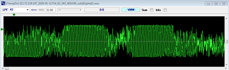
Most likely modem instability is the cause of the distortion in the manipulation speed (~42 bps), as it's evident in SA raster.


https://yadi.sk/d/qT-d1A_5bFtJHg

29 September 2018

HF Industry website (HFIA)

WARNING: some of the recent posts have links to the "meetings & presentations" section of the High Frequency Industry Association (HFIA) website that end up giving the 404 error "page not found". The "404" errors are not due to my errors in the links but to the fact that HFIA has recently changed the layout and the policy  of its website, and in particular the "meetings & presentations" section has been replaced by "resources" and is no longer browsable without an account.

the old layout of HFIA website


30 May 2018

T207_test

Finally a useful and fast tool to check the presence of T207 encoding in FSK bitstreams. The tool T207_test runs on Octave, a programming language for scientific computing, and was originally - and roughly - coded by me and then optimized and speeded-up by Christoph:

The script builds a n x 14 test matrix and for each row computes the number of "1" bits in the first 12 columns; then check if the 13-14 bits value is the one expected according to the table below. Since the 2-bit 'checksum' can occur everywhere within the 14-bit frame, the stream is shifted up to 14 times building a new test matrix at each shift. The script counts the success checks for each test matrix and display the results. The better test matrix is also plotted along the frame start offset (ie after how many shifts).


19 March 2018

WI2XER, Skycast Experimental Radio Station?

Few days ago, 16 March, I spotted on 7703.0 KHz/USB (cf 7704.8) a transmission consisting of 30 unmodulated tones, 100Hz spaced, lasting 20.7 secs and followed by Morse ID “WI2XER”. I wonder if it’s related to the Experimental Radio Station (ERS) run by Skycast. Quoting SWLIng "Skycast (WI2XER) is a station in the Experimental Radio Service, licensed under Part 5 of the FCC Rules."
Skycast recently renewed the license so probably they conduct test also in the 7 MHz band:
I tried to email Skycast asking a confirm of the intercept, so far no reply.


updates

April, 6 Spotted on 12140 at 1342z


April, 4  Spotted on 113905.5 at 1304z


29 October 2017

Maritime Interdiction Operations (MIOs) in Med'sea, a joint exercise?


The heard communications concern a Maritime Interdiction Operation (MIO) in Mediterranean sea and involve 2 vessels and one ashore station which acts as the net-control station by coordinating all the activities. It is not clear if  the heard activity is part of a routine patrol or rather a naval joint exercise. The ALE IDs used in communications (ie "CMOC", that could stands for Combined Maritime Operation Center), some terms in the messages (such as PUBEX, EVOLEX) and the "special" email domain name (here not reported for confidentiality) make me think to a MIO joint exercise. By the way, I did not find any related news in some specialized websites neither in press-agency sites.
The activity was heard on 7 and 8 MHz bands, expecially on 27 October. Communications  make use of 188-141 2G ALE for link setup while the messages are sent using a battle force email system based on STANAG-5066 HBFTP protocol. STANAG-4539/MS-110A are used as bearer HF waveforms, mostly QAM-64 9600bps and PSK-8 1200bps modulations (Figs 1,2). The STANAG-5066 addresses of the network nodes belong to the dummy block 10.000.000.zzz  which is not assigned to a country.
The language used for working out operational documents and for communications is English and French, this could be another hint in favour of a joint exercise.

Fig. 1 - STANAG-4539 transfer using QAM-64
Fig. 2 - STANAG-5066 stream
In addition to text or routine messages such as request to compress photos ("compresser la photo svp"), link informations ("liaison XXX to YYY par HF est nulle") or some ehortations ("veilles respecter le battle rythme et nous transmettre la situation RMP TN/DZ et vos position 12h00"), I saw some operational messages that are worth seeing. Although it could be a joint exercise, I avoid to go into details and some parts of these messages, as well as callsigns, are obscured or omitted for reasons of confidentiality of sensitive information. 

The firts two messages are related to the operation (tactical instructions?) and to the use of the MIO Board.

Fig. 3
Fig. 4
In Fig.5,  looks like they send informal ACP-like messages using email: note the from CMOC (Combined Maritime Operations Center?) to OTC (Operational Training Center?) header

Fig. 5
The operation was successull since the report on the interception of a boat of narcotrafficants (Fig. 6). Drug smugglers have thrown the material off at sea but it has been recovered by the navy sailors. Note how such reports are rigidly formatted in sections (termed "alfa", "bravo", "charlie") and sub-sections.

Fig. 6
Note also that in some messages, likely the more important ones, they make use of return receipts, as indicated by the MDN (Message Disposition Notification) tags in the email shown in Fig. 7 (turnaround time of 31 secs.). I saw MDNs in both English and French language.

Fig. 7
Many joint exercises (Phoenix Express, Morjane, Osis, MEDEX,...) take place every year in Souther Med'sea, so what I heard could be an ad-hoc scenario just established for this exercise.

update: 31 October 2017

...as expected:
http://en.aps.dz/algeria/20899-naval-force... 


16 January 2017

PM-SA, the Poor Man Spectrum Analyzer

This is a workaround to get a spectrum-analyzer tool for people like me who run 32-bit PC (real spectrum-analyzer need 64-bit systems).

The idea is to capture and store the SDR spectrograms (the waterfall) at fixed time intervals while the SDR is recording. When the recording time is elapsed, you may browse the saved screenshots and once you detect a certain signal you can access directly to it through the I/Q recording using the timestamp of that signal (which is printed in the waterfall). My test are with SDR-Console v2.3 and 20/20 v2.2 software, the latter is the programmable screen-capture tool.

setting the 20/20 v2.2 software

First of all, 20/20 v2.2 need to be executed as windows-95 compatible (Fig. 1)

Fig. 1
 
Run 20/20 v2.2 and hit files-> preferences to set the output directory and file, auto save, image format, and auto-increment as in Fig. 2 then set the capture-parameters paying attention to the Timed Options, Capture Target and Capture To (Fig. 3).

The most important value is the Timed Options: the Time Capure shall match the time needed to fill the SDR waterfall (better few second less so to get a little overlapping between two consecutive captures). In my case I preferred 60 seconds and then I will have 60 screen-shots/hour. Hit Ok and 20/20 starts.

Fig. 2
Fig. 3
setting the SDR software (SDR-Console v2.3)

The most important settings are intended to adjust the waterfall speed and height. In my opinion, 10 lines/second is the better resolution value, allowing to fit the waterfall in about 60 seconds (Fig. 4). Remeber that the time needed to fit the waterfall shall match the Time Capture value in Fig. 3! Note also that you have to set Add timestamp option in SDR-Console (Figs 5).

Fig. 4
Fig. 5
Once found the best values and window heigth, you may start the recorder after setting the duration of the recording (Fig. 6).

Fig. 6
Now you may go for a walk or at your job, stay with your partner, have a fresh beer or simply go to sleep: 20/20 & SDR recorder will do the job for you, once recording finished you will have the chance to analyze the stored waterfall screen-shots.


Analyzing the spectrum

Remember to stop 20/20: it run in background, saving screen-shots at the scheduled time. Browse the directory where 20/20 stores the screen-shots, as indicated in Auto Save (Fig. 1), you will see something like Fig. 7

Fig. 7
Images can be seen one at time, back or foward, using the Windows images viewer or some other similar tool. This way you may carefully examine every single “capture” using also the zoomer. At the same time, run SDR-Console and playback the recordered I/Q file (Fig. 8) keeping it paused. Minimize the SDR-Console window.

Fig. 8
When you see an interesting signal (unknown or maybe known by its shape) in a certain stored screen-shot, you have to write down the related timestamp and go to the SDR-Console window. Now, working with the playback navigator you have simply to access to the time slot which is related to the seen signal and play it, i.e. as shown in Figs. 9,11 (the being analyzed screen-shots) and 10,12 (playing the needed time slots from the I/Q file). Pay attention to the different time-format in the captured screen-shots and I/Q file!

Fig. 9
Fig. 10
Fig. 11
Fig. 12
20/20 v2.2 can be downloaded from:

(googling for it ...you may turn up an XXX site).

A better tool for screen capture is "autoscreen" (Fig. 13)

Fig. 13
You can download the software from:
https://sourceforge.net/projects/autoscreen/


ake screenshots automatically while you work and play! You can either use the interface or run it from a command line. The application ("autoscreen.exe") is a self-contained executable (which means there's no installation required) and sits in the system tray while it takes screenshots in the background without prompts or annoying pop-up messages.
The executable is only 209 KB in size so it can fit on a small (or a very old) USB thumb drive.
You can schedule to have screenshots taken every hour, minute, second, or millisecond. You can also specify what days the scheduled screenshots should be taken. The calendar enables you to see what days screenshots were taken. Remeber to un-check the "demo-mode" box !