27 April 2023

Thales mixed-mode traffic

Just a couple of comments about the different waveforms that can be seen when analyzing traffic exchanges performed using Thales equipment. 

1. As you see in Figure 1, after the proprietary Systeme-3000 Skymaster ALE, data are transferred using STANAG-4285 FEC and the HDR Single Tone waveforms (both proprietary) and even STANAG-4539. That's a bit unusual since, once link negotiation is complete, the  selected traffic waveform shall remain the same during that link session (apart FEC coding, interleaver and data rate).

Fig. 1

The order in which the different waveforms appear does not seem "formalised", probably it's due to the adaptive feature of the modem - which therefore adopts different data rates and waveforms - or it's in some way "announced" during the link negotiation. In this regard, the "dual demodulation state" comes to mind, a characteristic of 3G-ALE indicated in STANAG-4538: ie, the nodes partecipating in packet data type links do not expect a same waveform and are ready to demodulate  specific xDL waveforms. Looking at Figures 1,2, it seems that shall nodes be required to simultaneously demodulate at most four waveforms within the same logical link, ie they look for STANAG-4285 FEC and HDR ST (Thales proprietary) or NATO STANAG-4539, and obviously the ALE waveform signaling the link terminate. I don't know how this happens but I would guess the ALE phase announces what waveforms will be used.

Fig. 2

2. As from STANAG-4539 #4.3.1.1, the synchronisation preamble consists of two parts. The first part consists of at least N blocks of 184 8-PSK symbols to be used exclusively for radio and modem AGC (also known as TLC section). The value of N is configurable to range from values of 0 to 7. The second section consists of 287 symbols. The first 184 symbols are intended exclusively for synchronisation and Doppler offset removal purposes while the final 103 symbols also carry information regarding the data rate and interleaver settings. The total duration of the sync preamble as a function of the number N is shown in Table I.

Table I - sync preamble duration Vs N (at 2400 Bd)

In all the recordings at my disposal I noticed the same duration of the synchronisation preamble, i.e. 349.5 msec which correspond to N = 3 or three 184 symbols blocks for the TLC section (Figure 3): this - of course - is just a mere common peculiarity but which at least so far has not been denied in similar recordings (Thales). Other S4539 recordings I have analyzed have different preamble sync lengths. As specified above, the value of N is configurable, however it is not clear if this parameter is accessible to the operator or if it is a factory setting (however modifiable).

Fig. 3 - some Thales STANAG-4539 synchronisation preambles

Thales engineers certainly have the ability to modify the STANAG-4539 preamble, as in the case of the extended preamble employed in their Salamandre HFXL waveforms, however even military grade modems such as the Harris RF-5710A are able to recognize and demodulate these S4539 bursts, assuming that the data rate and interleaver settings values that are "read" by the modem are actually the exact ones

Fig. 4 - my Harris RF-5710A working Thales mixed-mode recordings

Such further recordings and comments are very welcome.

https://disk.yandex.com/d/yHtrobzZUhB2yA
 

18 April 2023

LDL 139-byte packets

For a few days I have been following the 3G traffic that takes place on 6682.0 KHz/USB and I have noticed that many of the transfers are exactly the same length (139 bytes) and follow the same sending formality, ie the protocol used is LDL (3G-HF STANAG-4538) and are retransmitted twice within the same link session.

Fig. 1

The caller node issues a 2-way FLSU_Request Protocol Data Unit (PDU) which conveys the caller node address,  priority, and the desired traffic service (packet or circuit mode). The called node responds with a FLSU_Confirm PDU, indicating the ability to continue with the requested traffic service. As it's known, FLSU protocol use the BW5 waveform.
Both the caller and called alternate sending LDL PDUs, with the caller sending data using the LDL Data Send PDU (BW3), and the called responding with the LDL ACK/NAK PDU (BW4).  This process continues until all data has been transferred error-free, as indicated by the caller sending redundant LDL End Of Message (EOM) PDU’s. Immediately after the LDL transfer is complete, both stations iunitiate the Fast Traffic Management (FTM) protocol to negotiate further traffic. This gives the called node an opportunity to send data in the reverse direction. After a the Link Timeout has occurred, the last station to receive an LDL transfer terminates the link by sending an FLSU_Term PDU. It's worth noting that after the EOM PDUs, both nodes remain linked (!) and given that the caller has already completed its data transfer, it is up to the called node to deliver any packet traffic it has, or to terminate the link if it doesn't have traffic to send. Note that:
- the EOM PDU indicates to the receiving station that the data transfer will be terminated;
- the Term PDU indicates to the receiving station the sender’s departure from the current link.
in EMCON scenarios the link termination is up to the caller node

Fig. 2

In these recordings, packet-mode service and LDL160 protocol are used. Before analyzing the bitstreams let's see how an LDL packet is built.
The "original" datagram to be sent is split into fixed-length segments which will be processed into packets by the chosen LDL protocol. An LDL data packet is defined as a fixed-length sequence of n-byte data segment (n = 32,64,96,...,512) followed by a 17-bit Sequence Number plus an 8-bit Control Field (presently unused). During the construction of the LDL BW3, a 32-bit Cyclic Redundancy Check (CRC) value is computed across the  data bits of each data packet and then appended. Then, 7 flush bits having the value 0 are added to ensure that the encoder is in the all-zero state upon encoding the last flush bit. Sumarizing, the on-air length of a LDLn burst is computed in bit as 8n + 64 (n = 32,64,96,...,512 bit), in this case (LDL160, n = 160) 1334 bit or 168 bytes.
That said, lt's go back to two decoded LDL packets (belonging to the same link session) by inspecting their last 64 bits (17-bit Sequence Number + 8-bit Control Field + 32-bit CRC + 7 flush bits):

Fig. 3

Let's try to analyze the 139 bytes messages. As indicated by the value of the bits 5-0 (all 0s, Packet Number #0) and SOM/EOM bits (all 1s) the original datagram consists of only one packet, the Packet Byte Count field (bits 14-6) indicates that the user bytes are 139 thus the remaining 21 bytes are filled with 0s.

0000000000000000000000000000000010000000100000001011010001111000
0110101001111000011010100111100001101010011110000000000001011000
1011101001011000101110100101100010111010010110001011101011010010
1010001111010011100111110000100101010011101000110011010010101101
0110100100111000000101000100011001100010011001010001100010111100
0110010010100001001101111111111100011001101100011001010001010011
1001010110000111011010110010100100001001110101111101000100100111
1010110000001010010010100101011000010100000001000100011001110110
1100110001101100001101110001011100011010110101101010010101010101
0001011010001100000011010111111111110110111000110001111001111110
1101100010101100011000010000111011001100111001101101011110011010
0111111010011110001001000010011100100000000010101011100111010110
0110111110101011111110110100010001110011100001001010100001100101
0011000110100011000111111011111101011000111001001010010101011100
0111010011110011000010100011010001111110100101101001100101001010
1010001000110100111100000101011110100010010110111101001101000101
0001110110100001011010010111100001101010011110000110101001111000
0110101001111000010000000000000000000000000000000000000000000000
0000000000000000000000000000000000000000000000000000000000000000
0000000000000000000000000000000000000000000000000000000000000000
0000000101000101110110111001010011111111001011110000000000000000

The analysis of the bitstreams shows that each datagram is always sent twice (Figs 4,5): I don't know if it's due to a negative ACK sent back by the reiceiver or rather a usual way of doing to give redundancy and reliability to the system.

Fig. 4
 
Fig. 5

After the removal of the 31-byte encapsulation added by the Harris "Citadel" cripyographic engine

00 00 00 00 01 01 2D 1E 56 1E 56 1E 56 1E 00 1A 5D 1A 5D 1A 5D 1A 5D (header)
1E 56 1E 56 1E 56 1E 02 (tail)

the resulting datagrams consist of 108 bytes. Such messages are very frequent(!), also sent using the circuit-mode service and MS-110A as traffic waveform. Sometimes it's occured to see that the 139-byte encrypted message is split into five packets and then sent using LDL32 [1] or even 9 times repeated using LDL160 [2], as shown in the Sequence Number fields in Figure 6

Fig. 6

https://disk.yandex.com/d/Ug94lJ40coIUDg

[1] https://yadi.sk/d/PvOS5FbM3H96Wz
[2] https://yadi.sk/d/_SCU3U073GzPf9

11 April 2023

the so-called "semi-modes"

Below an interesting article by SergUA6 (RIP) from radioscanner.ru about MSK, GMSK, SDPSK, and OQPSK: more info and examples here:
http://signals.radioscanner.ru/info/item68/ 
http://signals.radioscanner.ru/info/item281/ 

The "two-faced" signals, such as MSK and GMSK I name semi-modes, of course, it is not the standard name. It simply was required to allocate somehow this class of signals from the general PSK family, because such signals possessing both PSK signs and FSK signs.

The second harmonic of these semi-modes, has two bright spectral lines, the spacing between these lines is equal to Br, that is one of the signs of these modes.This is the necessary condition of their definition at the analysis, but not the sufficient one. Two lines in the second degree/power can be also given by both SDPSK and OQPSK modes.

SDPSK, generally, does not demand synchronism of transitions in extremums of the carrier, and because of this, it has the bigger width of the spectrum than MSK. This width of the spectrum can be reduced by filtering of the bit-stream before feeding on the modulator, this procedure is usually realizing through RRC filters. SDPSK (PSK-2 with phase rotation) in essence, has same resulting signal as MSK, only with wider spectrum. It can also be demodulated by FSK demodulator, becos of getting under definition of semi-modes.

Modern methods of creation of the various signals do often erase the distinction between various modes, for the reason, that developers are almost always (it strongly simplifies development) aspire to select a multiple relation between the clock frequency of manipulation and the frequency of the carrier.
In this case developer declares and forms, for example,that the modulation is SDPSK, but the resulting signal, in essence, is MSK. Thus, casually or deliberately some confusion is brought into diversity of the various modes and their definitions.

Very often GFSK modulation is specified,in descriptions of the signals, while in actual fact it is typical SDPSK according to all signs. The example is the signal of the Finnish radiosonde.
When we are looking at the circuit of formation of GFSK modulation, it is easy to understand that if the clock frequency and the generator will be synchronized, and the frequency spacing will be choosen as BR/2, then such “GFSK” will easily turn into one of our semi-modes, at defined parameters of Gaussian filter and high stability of generator’s parameters. Seems like developers just don’t think about it or just do not know.
By the way, in one’s time, by this reason, GFSK was mistakenly classified to these semi-modes on one of sites the modulation ACARS VHF has been declared as GFSK.

In analysis it is very desirable to define what type of modulation is used, at least approximately. It is also necessary to be oriented on the width of the spectrum, which is occupied by the signal and on its form. At pure MSK modulation, width of the spectrum is about 1.5*Br, at GMSK spectrum is lesser than this value, and in it’s limit is very close to theoretical Br, at the same time the spectrum of MSK, GMSK is obviously expressed as bell-looking-like shape/form, at SDPSK the spectrum is more then 1.5*Br. The basic sign of semi-modes is two lines in the second degree/power, the basic but not sufficient, it demands certain accuracy and attention. The spectrums form does also require certain accuracy, because often receivers distort it to unrecognizability, especially if the signal is taking off from AF’s output or from discriminator, in this sense it is much more preferable the I/Q record or IF.

Good luck!

30 March 2023

S-4538/110A transfers using 256-bit Initialization Vectors (2)

Recently I analyzed an interesting recording sent me by my friend Mike (mco) some days ago; for clarity, the transmission was recorded on 8006 KHz/USB. As shown in Figure 1, the recording consists of four data segment sent using the 188-110A Serial Tone (at 600bps/S), two 188-141B async call PDUs ("obsoleted", 3G-ALE)(1) and a final FLSU (Fast Link SetUp) PDU that terminates the link, the latter BW5 waveform suggests a STANAG-4538 3G-HF "circuit mode service" transmission, as well as the use of the 141B async call suggests the use of Harris equipments.

Fig. 1

The bitstream after 110A removal (Figure 2) clearly shows the use of encrypted frames which are characterized by the use of 256-bit length Initialization Vectors (IVs), thus the data-link protocol is also encrypted (not the data only). It's to be noticed that each Initialization Vector is 8 times repeated.
 
Fig. 2

The frame structure appears almost the same of the one analyzed in a similar transmission analyzed some times ago [1], in that case the 110A modem was used at 2400 bps/S. Studying more closely the four bitstreams, it's possible to see recurrence of a same COMSEC preamble consisting of 01s sequences for bit phasing, same repeated sequences (probably for frame sync), and obviously the four different 256-bit length Initialization Vectors (Figure 3).
 
Fig. 3

phasing

223-bit sequence sync:
0101101111011010010000100011110110111101110000100100001111000100010111011010001110100101101110111
1011100001001000011110001000101110000100011101001011011101111011100001001000011110001011010001001
00001110111101101000100011110

256-bit Initialization Vectors, each 8 times repeated:
E7 F6 45 FD 63 53 2A 4B 91 0B 0E B7 A8 80 00 00 
63 35 D7 73 64 9B 8D 08 35 3F 26 0D 9D BE 02 F9 

D7 32 3B 83 D0 6F 57 03 A9 65 CA F7 64 64 00 00
9B 32 8E B9 2B D0 9D D6 00 FB 96 53 68 92 BD F5 

87 32 AA F0 9C 3D 03 EE E2 00 26 EF 45 4D 00 00 
82 8F C3 CC BF 2B 36 99 51 27 45 88 9D 83 2E F7 

77 CD 93 E5 EB AF 65 3D B6 2B 1A 47 4E 19 00 00
C6 E1 5C FA 8B 16 57 57 0E 2B 04 C9 65 66 25 F3

phasing

32-bit sequence sync (6 times repeated):
8B 87 84 7B

The COMSEC preamble is followed by encryption, according to the standard MIL 188-220D [2].

Fig. 4
 
For what concerns the encryption, I would speculate the use of "HC-256", a software stream cipher for embedded systems which generates keystream from a 256-bit secret key and a 256-bit Initialization Vector [3], but it's just a guess.

 
(1) 188-141B (released on March 1999!) was superseded by 188-141C (December 2011), in its turn superseded by 188-141D (December 2017): the last two standards no longer have the Appendix C but only some short paragraphs, among them the #C.6 says "The specifications previously contained in this appendix have been replaced with reference to the essentially identical NATO STANAG 4538". 

[1] https://i56578-swl.blogspot.com/2020/09/s-4538110a-transmissions-using-unid-256.html
[2] http://everyspec.com/MIL-STD/MIL-STD-0100-0299/MIL-STD-188-220D_CHG_NOTICE-1_24817/ 
[3] https://www.ecrypt.eu.org/stream/ciphers/hc256/hc256.pdf 

15 March 2023

unid 188-110A transmissions... and equally curious bitstreams

Some interesting transmissions were noticed last weekend on 5074.20 KHz/USB, transmissions consisting of continuous blocks of different durations and sent using the standard MS-110A modem with a fixed data rate of 1200 bps/S. Judging by the intensity of the signals and the fading patterns shown in the FFT-Spectrum, the transmissions were one-sided, ie PtP or PtMP (like a broadcast style).

Fig. 1

Analyzing the resulting bitstream after the demodulation of the signals, surprisingly, it can be noted that one bit is replaced by 16 bits during the reversals section (Figure 2).

Fig. 2 - 16-bit stream

However, looking more closely, it can be stated that the 1->8 replacement is adopted during the traffic period, i.e. each data bit is sent 8 times (Figure 3).

Fig. 3 - 1to8 bit replacement during traffic period

In order to get some more information, I reshaped the bitstreams to a 8-bit format and then removed the 7 extra bit columns: as you can see in Figure 4, not all the single transfer sessions have a same period, indeed it may vary from 91 to 111 bit. 

Fig. 4

Also, for some reason that I do not know, there are very few single bits of information, just pairs 11s or 00s; just for a try I arbitrarily replaced the pairs with  single bits of the same value: the resulting stream, after the removal of the reversals sections, shows 60-bit patterns. I also tried the differential decoding but I didn't get any other interesting results about the nature of the data and the used transport protocol. My friend cryptomaster, who too heard and analyzed that transmissions, got the same results.
The working frequency (5074.20 KHz/usb) is not among those known or at least it is not reported on the UDXF logs, and given that the transmissions have not been repeated and the strange characteristic of the bitstreams, it could also be test transmissions.
What is certain is the geographic area where the Tx site is located: all the direction finding tries (TDoA method) point to the state of Lower Saxony, Germany (Figures 5,6).

Fig. 5

Fig. 6

I just want to report that a similar stream has been noted in some STANAG-4285 transmissions [1]: maybe these "expansions" are used to add redundancy and then increase the reliability of the channel, although HF protocols use their own FEC encoding.

https://disk.yandex.com/d/QgDFohyS8dqeVg

[1] http://i56578-swl.blogspot.com/2022/01/an-odd-16-times-expanded-5n1-framing-uk.html?m=0

13 March 2023

RapidM proprietary WB-LDL & WB-RDL waveforms (2)

Thanks to a nice catch by my friend ANgazu from radiofrecuencias.es, who I thanks, it's now possible to add two other waveforms (#9, #11) to the Table II of the previous post [1]. The waveforms belong to the "120 ms frames" family, respectively 30 KHz bandwidth 24000 Bd (WF #9, Figure 1) and 42 KHz bandwidth 33600 Bd (WF #11, Figure 2).

Fig. 1 - 30KHz/24000Bd waveform

Fig. 2 - 42KHz/33600Bd

https://disk.yandex.com/d/o8htpYuX7xSXuw

[1] https://i56578-swl.blogspot.com/2022/12/wale-wideband-traffic-probably-rapidm.html


23 February 2023

unid "mixed-mode" transmission

 updated

 Very interesting "mixed-mode" transmission cathced and sent me by by friend Michel (F1GOC)

Fig. 1

Segment 1 consists of an FSK modulation keyed at 200 Baud and 1000 Hz shift (Figure 2). The demodulated bitstream has a well defined period of 288 bit consisting of a data segment preceded/followed by a sync/probe sequence (Figure 3).

Fig. 2
 

Fig. 3

Segment 2 consists of an MFSK-7 modulation keyed at 30 Baud and 400 Hz separation between the tones. The raw demodulation of the seven tones (0-6;000-110) shows a repeated sequence of 940 bit length (Figures 4,5).

Fig. 4

Fig. 5

Segment 3 is the most interesting one. This segment consists of 7 subcarriers which coincide with the tones of the previous MFSK segment (see Figure 1), the modulation used for each subcarrier - in my opinion - seems to be ASK2/OOK. The "aggregate" speed of modulation is 200 Baud, ie 28.5 Baud per channel (Figure 6). The autocorrelation function of the signal shows a period of 10 seconds, corresponding to 2000 bit frames (Figure 7).

Fig. 6

Fig. 7

As a simple curiosity, the central frequency of the FSK segment does not coincide with the value of the center band of the following two segments (see Figure 1). Difficult to state the user and the purpose of the transmission, many "experimental" signals are in the air especially during this period, comments are welcome.

------- update  --------------------------------------------------------

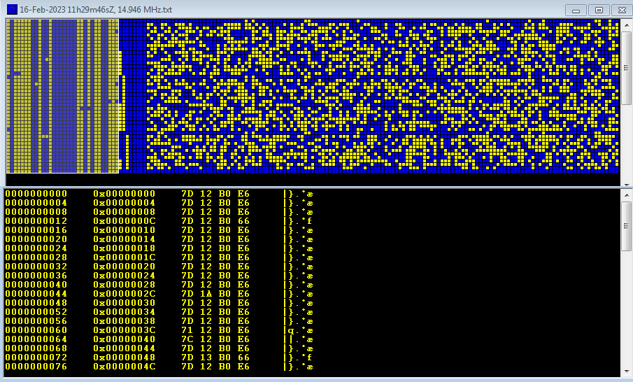
As my friend cryptomaster commented (and my friend Nicola too in pvt), the FSK segment is the well-known Russian Intel "F06" waveform. Indeed, after the change of the bit-order is possible to clearly see the typical F06 32-bit sync sequence 7D12B0E6 (Figure 8). The final part of the decoding, thanks to the rivet_b90 tool, is shown below (Figure 9). 

And... yes, I'm a bit out of shape since the 288-bit period should have suggested the solution 😁

Fig .8 - F06 sync sequence
 

Fig. 9 - F06 decoding

https://disk.yandex.com/d/2hsIqrswtSwzHw

1 February 2023

unid ASK2/OOK transmissions

updated

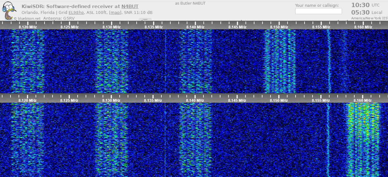
Unid transmissions heard on 8120, 8130, 8140, and 8150 KHz (the latter moved to 8160 Khz) thanks to the KiwiSDR located at N4BUT Orlando, FL [1].

Fig. 1

At first sight the signal seemed a MPSK modulation, but working the signal along with my friend cryptomaster some other interesting features came out. Each transmission consists of four 100 Hz separated channels (a,b,c,d) each occupying a band of about 900 Hz, for a total bandwidth occupation of about 3900 Hz (Figure 2).

Fig. 2

In turn, each of the 4 channels consists of 4 sub-channels with a modulation rate of 49.6 Baud, the used modulation seems to be ASK2/OOK [2].

Fig. 3

Each of the four sub-channels shows strong ACF peaks of 1290 ms corresponding to a 64-bit length frame: the "aggregate" frame therefore has a length equal to exactly 1 Kb, ie 1024 bits or 128 bytes (64x4x4).

Fig. 4

Below in Figure 5 is a comparison of the four channels obtained from the analysis of my friend cryptomaster.

Fig. 5

Although I have kept an eye on that initial portion of the 8 MHz band (fixed/mobile band, shared with marine for simplex purposes), those transmissions have not appeared again (at least until today): difficult to define their purpose and user(s).

Below the interesting comment sent me by my friend Nicola, who I thanks for the collaboration:

"The interesting signal discussed in the blogpost “Unid ASK2/OOK transmissions” dated 1 February is probably a Frequency-Time Matrix (FTM) system, where a data symbol (bit string) is represented by FT-matrices, i.e. combinations of frequency and time domain positions. The 'secret' of this robust mode is that no frequency is repeated within each matrix. This characteristic is used to enhance the resilience against frequency domain broadband noise (or fading) affecting a broad range of frequencies and time domain narrowband noise (or fading).

https://disk.yandex.com/d/7u74pzY-bPntXg

[1] http://sdr.n4but.com:8173/?f=8120.00iqz10&pbw=10000
[2] https://en.wikipedia.org/wiki/Amplitude-shift_keying

16 January 2023

4529.75 KHz (cf), yet another async 5N1 STANAG-4481F (to replace 4539.7 KHz?)

Some days ago my dear friend Karapuz noted the transmission of STANAG-4481F segments centered on 4529.75 KHz, data were transferred using 5N1 framing and apparently not in clear text. In the following days I monitored, albeit occasionally, the channel until the transmissions started to be continuous (Figure 1).

Fig. 1

Analyzing the bitstream after the start/stop bits have been removed, it turns out that the messages are sent in protected mode using KG-84/KIV-7 encryption... as it was expected since the used protocol (S-4481F, 75Bd/850). As already noted in other similar STANAG-4481F transmissions, the 128-bit Initialization Vector is splitted in two 64-bit groups and each group is repeated twice rather than four times (as instead it's used to do in STANAG-4285 transmissions).

Fig. 2 - notice the presence of the KG-84 64-bit sync sequence and the 128-bit Initialization Vector (after the removal of the start/stop bits)

As happened for the 4539.7 KHz channel, in the same way the 4529.7KHz channel started with test transmissions and then switched to the usual secured broadcast [1]. TDoA runs indicate the DHFCS site in Crimond UK.


 https://disk.yandex.com/d/6Q_7zvpMlBb8ow

[1] https://i56578-swl.blogspot.com/2021/09/async-5n1-stanag-4481f-likely-tests-or.html

31 December 2022

a curious AT-3400D/AT-3104 (CIS-12) modem configuration

Interesting catch of an AT-3400D modem (also known as CIS-12 or MS-5) running on 14344.0 KHz/USB with the quite uncommon 9 channel configuration (3-out-of-12) as shown in Figure 1 below

Fig. 1

CIS-12, as you know, is a pseudo OFDM 12-tone (+ 1 pilot) waveform using PSK2 or PSK4 modulation at speed of 120 Baud while the modem name is AT-3004D (or its newer counterpart AT-3104). Channels 1-10 are used for data, 11 and 12 are test/service channels, therefore the "aggregate" speed is 1200 Baud. 

Fig. 2

https://disk.yandex.com/d/HWWIfdAR6aLKuA