25 February 2022

STANAG-5066 over MIL 188-110A: SK AF messaging

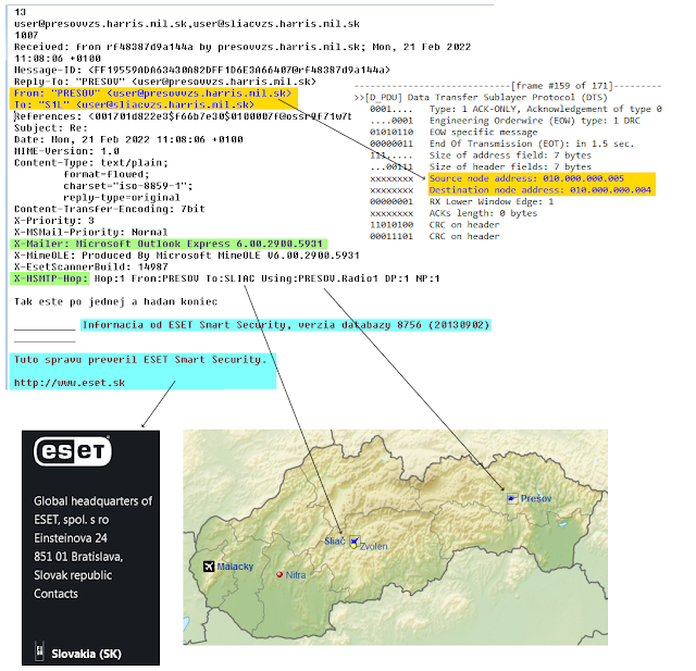
Slovakian AF communications spotted on Monday at 6343.0 KHz/usb, rather unusual frequency given the previous logs (actually first time heard on this qrg) and no more heard since last monday 21. The usual paradigm is used: ie, 188-141 2G-ALE handshake (S1L caller, P10 called) that is followed by the data forward by means of 188-110A ST modem and STANAG-5066 as datalink protocol.

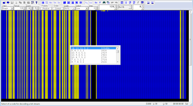
Fig. 1 - STANAG-5066 bitstream

No transport protocol is used since STANAG-5066 assumes the burden of message integrity within the HF network: indeed, the email file are compressed and then transferred from one SMTP server to another by using HBFTP (Basic File Transfer Protocol) as per Annex F of STANAG-5066. BFTP implements a very simple end-to-end file transfer protocol based on the ZMODEM protocol and shall be provided by STANAG-5066 implementations: in this case, the initial "H" could stand for Harris implementation. It's to be noticed that BFTP is connected to the RCOP (Reliable-Connection-Oriented Protocol) socket interface.
HSMTP (likely Harris SMTP, Simple Mail Transfer Protocol) routing shows that the recipient node is at 1-hop distance (DP and NP values).
The email addresses and other terms reveal that the messaging system software, and most likely the connected radios, are provided by Harris Corporation, almost surely the Harris RF-67x0W Wireless Gateway suite. 

Fig. 2

about users:
ALE callsign P10 (Stanag-5066 address: 10.000.000.005) is "prezovvzs", Prezov VzS
ALE callsign S1L(Stanag-5066 address: 10.000.000.004) is "sliacvzs", Sliac VzS  
("Vzdušné Sily" is the Slovakian for Air Force)
It must be noted that for "domestic" traffic they do not use their S-5066 Regional Assignee range 6.42.y.z but rather 10.x.y.z.
Also interesting is the use of ESET Smart Security, database version 8756 (20130902), to protect the systems against virus and malware. 

https://disk.yandex.com/d/5kVfxb1Y95_R2Q

17 February 2022

5N1 frames To 112-bit period stream (just for fun, again)

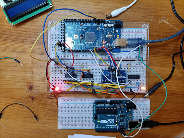
This post is the follow up, and the counterpart, of the previous one (112-bit T stream To 5N1 frames, just read it for background). If while receiving we need a "downsampling" by a factor of 16 of the 112-bit period stream coming from the modem, when transmitting we have to expand the source 5N1 frames bitwise by the same factor before to forward them to the modem. As in the "downsampler", I used the multiplexer/demultiplexer module CD74HC4067 and two I2C connected Arduino boards.

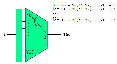
Each bit of the 5N1 frames is spread to a 16-bit D-type latch register which is three-state connected to the 16-input of the multiplexer, the inputs are then selected and forwarded to the multiplexer serial output at a speed that is 16 times faster than the 5N1 frames (figs. 1,2).

This way each input bit is 16 times repeated in the serial output and thus the stuf performs the 16x expanding. Not having a 16-bit register at home, I used two 74HC595 (8-bit, serial-in, parallel-out shift register that feeds an 8-bit D-type register).
 
Fig.1 

Fig. 2

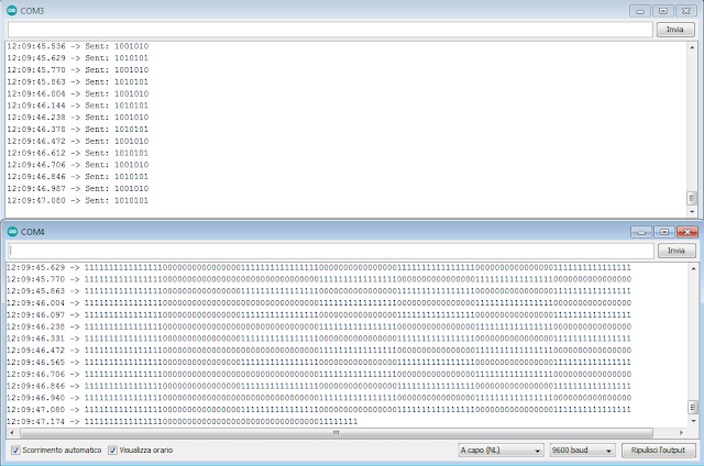
The 5N1-112 conversion is not done via software: a board takes care of sending data to the other one which forwards 'em and manages the ICs. Input/output data are dispalyed on the serial ports (COM3 on the sender, COM4 on the receive expander, see figure 3 below).

Fig. 3

As already mentioned in the cited post, I do not  aim to "replicate" the circuit used to perform the 5N1-112 conversion but only try to simulate its operation through the use of a multiplexer. For those interested in playing with the two circuits (...but I really don't think so) the 4 rough "sketches" can be downloaded from here along with the data sheets of the used ICs:   
https://disk.yandex.com/d/SVTcXiikai1VRQ 

11 February 2022

112-bit period stream To 5N1 frames (just for fun)

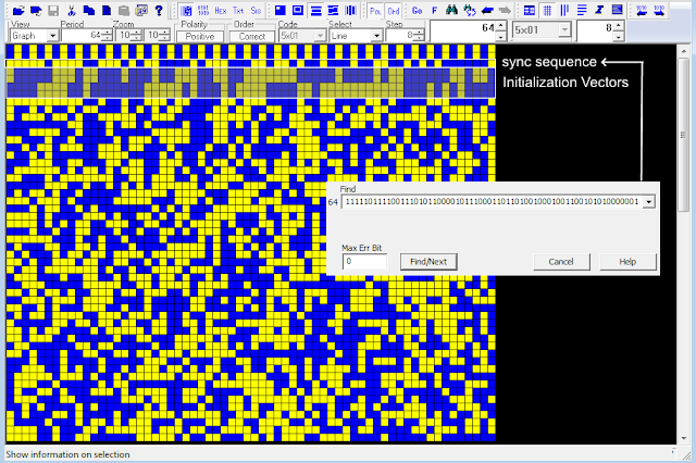
I recently re-thinked to the odd 112-bit period stream sent by UK MoD via STANAG-4285 and described  here, more than anything else I was intrigued by the "stuff" used for the manipulation of the streams. Looking at the bitstream of figure 1, one can see that either the sync sequence and the Initialization Vectors are 16 times bitwise expanded, thus that "stuff" shall sit in the middle between the crypto device and the STANAG-4285 modem, assuming that it is not embedded or implemented in one of the two devices. 

Fig. 1

During the receive phase it shall perform a downsampling of the received 112-bit period stream by a factor of 16 while in the transmit phase it will expand the source 5N1 frames bitwise by the same factor: in a few words, in some way the stuff acts like a multiplexer/demultiplexer (figure 2).

Given that:
Z = serial input/output 
Yn = input/output channels

Tx side (expander):
each input bit is applied to all the input channels and their selection speed is 16x the speed of the input bits, ie:
bit 00 → Y0,Y1,Y2,...,Y15 → Z
bit 01 → Y0,Y1,Y2,...,Y15 → Z
...
bit 15 → Y0,Y1,Y2,...,Y15 → Z

this way each input bit is 16 times transferred into the serial output and thus performing the 16x expander.

Rx side (downsampler):
The selection of the output channels is in sync with the input bits (same speed), ie:
bit 00 → Y0
bit 01 → Y1
...
bit 15 → Y15

since all the sixteen bits have the same value (1 or 0), it turns out that draining the output only from Y0 (or from any other single channel) we get the needed downsampling by 16.

Fig. 2

I started thinking about how that "stuff" could be implemented: software or wired-logic solution. The software solution is easy to code and may be based on a PC as well as on Single Board Computers such as Raspberry Pi or Banana Pi or also on microcontrollers as Arduino, obviously the serial interfaces are needed. Just as a Proof of Concept, and  to have some fun, I decided to to demonstrate the wired-logic feasibility with multiplexer/demultiplexer breakout board module CD74HC4067 and two Arduino boards connected via I2C communication bus in the Master-Slave configuration (1). 
 
In the downsampler Rx configuration (figure 3), one Arduino board ("Uno") acts as Slave and it's requested to send the 112-bit period stream, this board represents the output of the S4285 modem; the second Arduino board ("Mega2560") is the master and drives the dmux CD74HC4067:
• requests data to the slave and forwards them to the dmux serial input 
• selects the output channel Yn through the address bus S0-S3
• withdraws the Y0 output and forwards it to a LED (ie the following crypto device)
The master board also controls the HD44780 LCD which is added to display the received 5N1 frames after their downsampling ...almost useless since data are dispalyed on the serial ports (COM3 on the sender, COM4 on the receiver: see figure 5).
 
 
Fig. 3 - Downsamnpler Rx connections


Fig. 4 - downsampler at work

Fig. 5 - serial port monitor of sender (COM3) and dowsampler (COM4)

As aforementioned, this post is not intended to build the conversion circuit 112-5N1 but to simulate its operation through the use of a simple demultiplexer ... and to have some fun. In a next post I will also try the reverse operation 5N1-112 but always using the module CD74HC4067 this time as a multiplexer. By the way, I used the CD74HC4067 as it can be used both as a multiplexer and as a demultiplexer, in this circuit it can be replaced with the SN74154 (dmux only).  


(1) The I2C communication bus is very popular and broadly used by many electronic devices because it can be easily implemented in many electronic designs which require communication between a master and multiple slave devices or even multiple master devices. The easy implementations comes with the fact that only two wires are required for communication. The two wires, or lines are called Serial Clock (SCL) and Serial Data (SDA).  The SCL line is the clock signal which synchronize the data transfer between the devices on the I2C bus and it’s generated by the master device. The other line is the SDA line which carries the data.

7 February 2022

IoT on HF NVIS (tentative)

 I56578, ANgazu

The Antarctica department of La Salle Campus, Ramon Llull University of Barcelona has been carrying out studies for some years, among which we are interested in the communications part. They study remote sensing IoT communications using NVIS platforms, a very useful system in places where there are no mobile communications infrastructures and the physical conditions do not invite useless movements. They are also studying HF links between Antarctica and Spain, of just over 12000 km. To allow the sending of the appropriate sensor data, since many bases remain closed or under minimum during the Antarctic winter. These tests include testing with various modulations to try to find the optimal one for the application.
Regarding the tests in Spain. they use an NVIS link between the Barcelona campus and the Cambrils campus. As far as we know, they do the tests at 5400 KHz, taking advantage of the University's Radioclub that collaborates with the department.
At present, we guess they continue with the tests and we assume that the recordings we are making correspond to them. The use of NVIS antennas limits the reception possibilities, since the Alicante KiwiSDR is not operational. However, with the available devices we are recording signals and we hope that some of them will meet the necessary quality for their analysis.
We can see in the spectrogram (figure 1) that they use a bandwidth of about 12 Khz, a bit excessive for the signal parameters. 

 
Fig. 1

The blocks are transmitted between 1 and several minutes apart. There does not seem to be a regular structure. Every block is made up of 25 segments, although there are some 14 and 50. Each segment measures about 265 ms, of which 60 correspond to a continuous carrier that is about 600 Hz. above the transmitter carrier.

Fig. 2

The "current" framing of the segments is very different than the one described/used in 2018, see figures 3a-3b: its duration is 265ms and in my opinion the data part has a duration of 70ms and is followed by a 115ms (or better, 110ms + 5ms) pattern. 

Fig. 3a - current framing (the one we recently saw)

Fig. 3b - framing used in the tests carried out in 2018

Although there are some uncertainties and doubts in some segments the modulation used appears to be PSK4, but its analysis requires much more attention: at this regard I edited the signal and removed to 60ms tone as well as the ending 115ms segment (see figure 3a). Results are shown below, please note that the SA PSKn demodulator:
* does not lock on any sync sequence thus phase rotations are unavoidable
* it uses the following symbol mapping for PSK4 constellation:
0 (00) ==>  00°
1 (01) ==>  90°
2 (10) ==> 180°
3 (11) ==> -90°

Figures 4a-4b shows a standard PSK4 constellation with its regular and expected transitions between the four states, anyway figure 4c shows that the trajectories do not match the ones of PSK4 (figure 4d): ie, all the transitions are featured by zero-crossing paths like a π/2 rotated PSK2 (0<->180,90<->-90). Also note the slight "smudges" on the trajectories of figure 4c which led us to analyze the states by using a 8-ary constellation.

Fig. 4

Actually, we don't know how much sense an 8-ary constellation makes, since the modulation clearly "dances" around four states, anyway it's interesting to see the π/4 rotation of the transitions shown in figure 5b as verified by the trajectories shown in figures 5c,5d.

Fig. 5

That said, we demodulated the blocks using PSK4 demodulator and the mapping shown above: the resulting bitstream is about 914 bit (457 dibit symbols) which is compatible with duration & speed (205ms @2380Bd) of the bursts. At glance, it seems that each segment of a block transports the same data (figure 6).

Fig. 6

That's all at the moment, further recordings and analysis are obviously needed and hopefully some confirmation from the testers. Comments and tips are very welcome.

https://disk.yandex.com/d/qmm7aDnwWshq0w
3 February 2022

a curious STANAG-4285 transmission

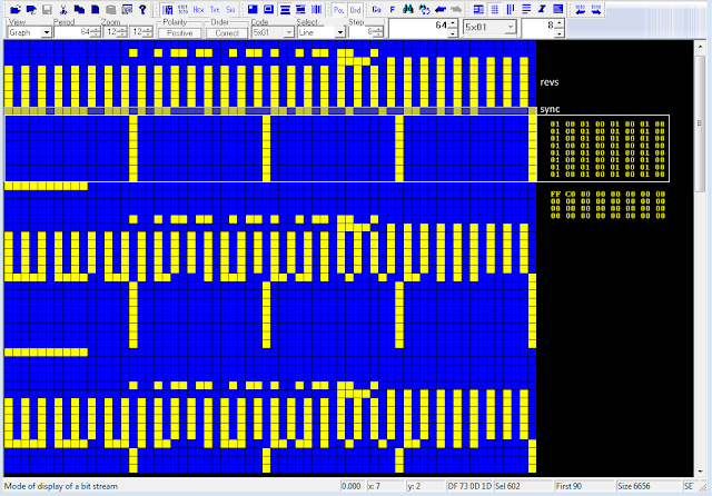
Really curious STANAG-4285 transmission sent me by my friend IK1YDE Andrea who was the first to spot and analyze the signal. The oddity is that, after S4285 demodulation, the Initialization Vectors, as well as being repeated within each message, consist of the unique(!) and a bit "basic" sequence: 0x0001000100010001 (see figure below).
Actually, KG-84/KIV-7 devices use 2 x 128-bit sequences as IV and these sequences - as well as in other crypto devices - change with each new message, even if the same message is repeated (in this case 0xFFC00000000000000000000000000000).  
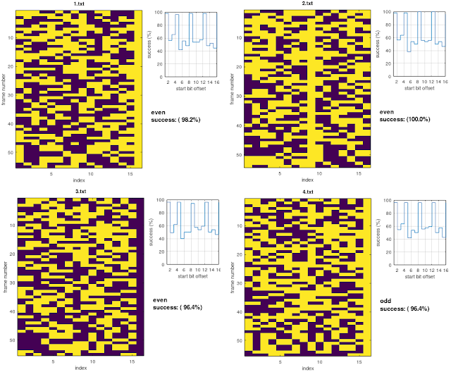
Fig. 1
 
Andrea heard that transmissions on 4165.6 KHz/USB, the only (Freq/Mode) match I found dates back to 2005 and refers to French-Ny FUE. No other interception in recent days, even if sporadically monitored.  No idea what this transmission is, maybe tests of new setup?

11 January 2022

odd 16 times expanded 5N1 framing (UK DHFCS)

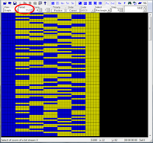
Rather curious pattern transmitted by the UK DHFCS site in Crimond on 4538.0 KHz/USB, reported to me by friend Linkz, using the STANAG-4285 waveform at 1200 bps/L submode: it's about a 16 times "expanded" asynchronous 5N1 stream (112-bit length framing, as shown in figure 1):

Fig. 1 - 16x 5N1 framing (112-bit period)

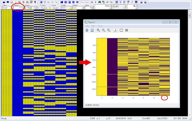
The source 5N1 framing can be obtained after removing the overhead bits: this can be easily done by manually editing the demodulated bitstream, for example with BEE, or by "downsampling" the bitstream by a factor of 16 using a simple script coded - for example - in Octave (figure 2).

function [a]=downTo16(fn)
  # pkg load signal before to run the script)
  # fn = filename containing a stream of ASCII 0's and 1's w/out spaces!
  a =[];
  k =7;
  fp =fopen(fn);
  fsk =fgetl(fp);
  fclose(fp);
  bits = fsk=='1';
  y =downsample(bits,16);
  n =floor(length(y)/k);
  a =reshape(y(1:n*k),k,n)';
  dlmwrite("5N1.txt",a," ");
  imagesc(a);
endfunction

Fig. 2

After "downsampled" the bistream  (ie reduced to its "natural" 5N1 framing) and removing the initials reversals and start/stop bits, it's possible to detect the KG-84/KIV-7M sync sequence as well as the two 128-bit initialization vectors, here twice repeated (figure 3). 

Fig. 3

Now, given the adopted frame's structure and the 1200 bps speed, it turns out that the actual data rate is 1200÷16 = 75 bps (!) and therefore it matches the speed of STANAG-4481F (obviously bps=Baud in case of FSK): it's worthwhile to note that such STANAG-44881F transmissions from Crimond had already been reported [1].  

KG-84 devices talk to each other at 75 bps

I don't know why such a 112-bit pattern is used: definitely it's not an error detection and correction measure (too high ratio codeword/data, 93.75%). Judging by the bitstream, the 16x stuff sits between the crypto device and the STANAG-4285 modem, one could venture the hypothesis of  a failure of the FSK modem and its (temporary?) replacement with that workaround (1200bps is their usual STANAG-4285 speed)... but it's just a mere guess.

Fig. 4 - DF results (KiwiSDR TDoA algorithm)

https://disk.yandex.com/d/3ZAITNGcf3qs5w
(the zip file contains the wav recording, the 112-bit demodulated stream and the Octave scripts downT016.m and upTo16.m, so you can play with them. A quick howto for installing Octave is here)

[1] https://i56578-swl.blogspot.com/2021/03/async-stanag-4481f-with-kg-84kiv-7.html

5 January 2022

Yet another 75Bd (actual 50)/850 FSK

Yet another 75Bd (actual 50)/850 FSK bearing KW-46 encrypted broadcast spotted on 5189.50 KHz CF, this time probably(?!) sourced from some France AF base (figure 2). The reason of that "format" is still unclear, at least to me (1).

Fig. 1

It should be noted that not all the French sites in figure 2 host HF transmitters, as well as the possibility of some uncertainties of the current TDoA algorithm in finding the origin of FSK signals (as suggested by my friend Linkz); figure 3 shows the Direction Finding results got with the "old" TDoA algorithm: results point the coast of south UK.

Fig. 2 - Direction Finding TDoA results

Fig. 3 - Direction Finding TDoA results (old algorithm)


 https://disk.yandex.com/d/nQZYpTLMq5mJwA

(1) https://i56578-swl.blogspot.com/p/75bd-actual-50bd-4481f.html

31 December 2021

UK DHFCS St.Eval running the Aus 600Bd/850 FSK waveform

Since a few days ago, approximately from the fourth week of December, on 2815.0 KHz (CF) it's possible to receive a strong and continuous 600Bd/850 FSK transmissions which is likely a fleet broadcast (figure 1).

Fig. 1 - 600Bd/850 FSK waveform

Transmissions are secured by KW-46 crypto devices; indeed, as per STANAG-5065, the 7-bit stream is featured by the M-sequence generated by the polynomial x^31+x^3+1 which substitues the stop-bits and acts as sync sequence for the receive KW-46, the remaining 6 bits are encrypted (figure 2).

Fig. 2 - KW-46 sync sequence

Regarding these broadcasts, there are two aspects that are worth underlining: 

a) that particular FSK format (600 Baud, 850 Hz shift) was recently adopted by the Australian Defense Force (ADF) MHFCS (1) to replace their previous ISB system. As a further confirm, these signals exhibit a quite unique sign when inspecting their harmonics: the presence of several spectral lines in the 7^ power, as shown in figure 3. It's to notice the lack of the "paired" 50Bd/850 FSK channel (operating 4 KHz above);

Fig. 3 - the harmonics in 7^ power

b) that channel (2815.0 KHz CF) belongs to the UK Defence High Frequency Communications System (DHFCS) and until a few before it was possible to receive on that frequency the ordinary fleet broadcast consisting of STANAG-4481F (75Bd/850 FSK) transmissions encrypted with KG-84/KIV-7 devices.

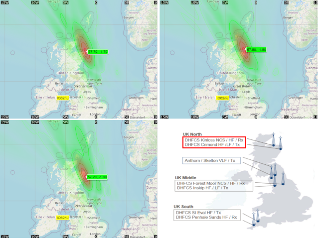
Given the probable location of the transmitter, I chose to run the Direction Finding tool using 'test' receivers near England; furthermore, given the frequency, I preferred to carry out the tests (TDoA method) in the morning to avoid wave reflections and therefore try to obtain results based as much as possible on direct wave reception. As expected, all the several DF runs point to an area close to the UK RAF site of St.Eval in Cornwall (figure 4): an HF transmitting station, with Penhale Sands as the associated receiving station, which is operated by Babock Defence Communication (as part of the Defence High Frequency Communications System) on behalf of the Ministry of Defense.

Fig. 4 - Direction Finding (TDoA) results

Therefore it can be said that the previous NATO STANAG-4481F (KG-84 secured) broadcast has now been replaced by the ADF 600Bd/850 (KW-46 secured) broadcast, both transmitted from the UK DHFCS site in St.Eval: that's a really curious "paradigm shift" in terms of FSK waveform and encryption (75Bd/850 → 600Bd/850, KG-84 → KW-46), don't know if it has something to do with the trilateral security partnership between Australia, the United Kingdom, and the United States (AUKUS), or it's some training/exercise. Anyway, I checked the FSK frequencies of DHFCS (at least the ones I know) to understand if this mode was also used in other channels but it was not successful. Frequency monitoring will give us more information.


 https://disk.yandex.com/d/BXLEeV10tp7gKg

1) Australian Defence Force (ADF) Modernised High Frequency Communications System (MHFCS) is a managed, long-range strategic communications system that enables the secure exchange of information, such as voice, e-mail, facsimile, interactive data and organizational messages, between fixed and mobile stations using one integrated system. 

23 December 2021

unid 500Bd/1000 FSK ARQ network

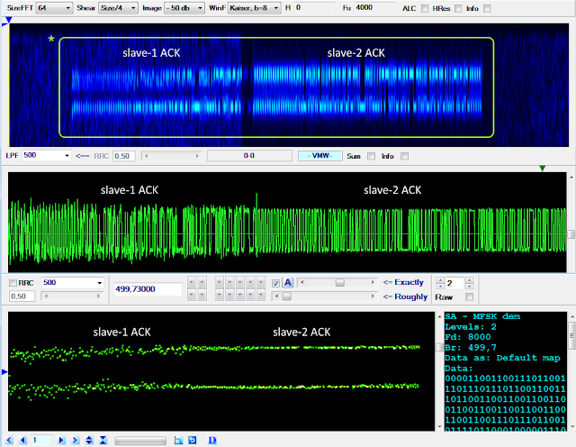
This is an interesting "Akula-like" FSK waveform spotted by my friend cryptomaster on 7370 KHz/usb (41 mt broadcast band!), the signals are keyed at the speed of 500 Baud with frequency spacing of 1000 Hz. The recorded session consists of messages (the longer segments) followed by short ACKs which are sent back from apparently two correspondents; ACKs partially overlap each other and sometimes they seem even superimposed (figure 1).  

Fig. 1 - FSK 500Bd/1000

The raw decoded streams of the messages show a 24-bit period length with a solid column of "1"s (or "0"s), the presence of the initial "0011" sequences in place of "01" clearly indicates that the signal is differential encoded (figure 2). Notice the violation of the bit reversal structure (a "1" is inserted instead of a "0") when the system transits to the traffic condition.

Fig. 2 - raw and differential decoded signal

After differential decoding, I found consistent matches for the scrambler described by the polynomial x^12+x^10+x^9+x^3+1 (or its equivalent x^12+x^9+x^3+x^2+1): after its removal, a common "area" of (at least) 253 bits emerges immediately after reversals (figure 3): most likely that's the preamble section which therefore consists of a 253-bit pseudo-random sequence (PRBS) which is part of the 4096 bit M-sequence generated by the aforementioned polynomial.  

Fig. 3

Removing the initial reversals from the differential decoded bitstreams, we are able to get and analyze either the data blocks and the preamble sequences: as expected, the latters are the same (figure 4).

Fig. 4 - 253-bit pseudo-random sequence used in the sent messages

The data blocks are even-parity checked (figure 5) and consist of 24-bit codewords each consisting of 23-bit length data sequence followed by one parity bit. Since the use of a single parity bit can't correct any error, my idea is that they could use a kind of (24,k) code with 24-k parity bits (EDAC bits). The identification of which particular code is used is not easy, it must be taken into account that the parity bits maybe dispersed in the codeword and the possible use of the bit-inversion technique as well as the order in which data and EDAC bits are arranged into the codewords.

Fig. 5
 
The identification of which particular code is used is not easy, it must be taken into account that the parity bits maybe dispersed in the codeword and the possible use of the bit-inversion technique as well as the order in which data and EDAC bits are arranged into the codewords. I checked the Golay(24,12) and Hamming(24,18) codes but unsuccessfully.
 
The ‘ACK’  packets are also differentially encoded. Their preamble is a pseudo-random sequence which is part of the same M-sequence generated by the aforementioned polynomial x^12+x^10+x^9+x^3+1; in this case, the minimum "common" area found after descrambling has a length of 251 bits (figure 6).


Looking at figure 7, the variation of the length of the initial bit reversals (260 and 980 ms) of both message and ‘ACK’ packets suggest that the messages are sent by separate modems. Indeed, listening to the recording it is obvious, that (at least) three different stations are present and that they seem to operate in half-duplex mode with one station at a time sending messages, and one or two stations responding, sometimes on top of each other.
Also notice in figure 7 the lack of ‘ACK’ after message B. This might indicate the deployment of a stop-and-wait ARQ mode, ie A packet is repeated until an acknowledgement is received. However, the decoded succeeding message C is not identical to message B.

Fig. 7

Please, also notice that the partial collisions of the ‘ACKs’ occur when the message transmitting modem is the one with a long run of bit reversals. Such a partial collision is much more evident in figure 8 where the existence of two slave modems can be clearly distinguished. This could indicate that this station is the master station of the network.  

Fig. 8

Due to the partial collisions, the shorter ‘ACKs’ as expected only exhibits part of the preamble sequence (figure 9):

Fig. 9
 
The hypothesis of overlapping modems is also supported by the examination of the SNRs of the two signals, as shown in figure 10 (thanks to "Audacity" free software [1]).
 
Fig. 10
 

Differential demodulation in chronological order of the recorded ‘ACKs’, does not offer much additional information other than a very varied 48-bit format (see figure 11). In the figure the lengths of the data sections are unequal. That format is due to the fact, that I somewhat arbitrarily used the beginning of the trailing bit reversal ("01") sequence (if any) as a delimiter; there is no obvious evidence of parity bits nor of particular patterns. Bit reversals and preambles have been removed.


So, judging from the observations described above, it seems that we are facing a more complex scenario than the simple two nodes in half-duplex, ie a network consisting of multiple (at least three) stations that exchange messages in ARQ mode, sometimes one sender and two correspondents at time, and sometimes just one correspondent.

With a cautious approach, I could imagine three reasons for the collisions:
a) They might be due to the fact that the correspondents sometimes are unable to hear each other and thus 'think' that it's their turn to transmit. However, one would expect a network with a master station broadcasting and several slave outstations responding to have a centrally determined schedule with fixed intervals preventing outstations from interfering with each other, somewhat like Link-11, or, even better, a GPS-synched network like STANAG-4538

b) It is also possible that the reason for these phenomena are seen as collisions are due to the location of the intercepting station in relation to the location of the network stations being monitored, which could give rise to differences in the propagation time at the interception site and the intended recipient

c) And, finally, the short ‘ACKs’ might be a combination of acknowledgement and request to transmit or changeover commands ('you next')
 
Further investigations are in progress... and thanks to my friend Nicola for the editing.

15 December 2021

Chinese PSK2 2400Bd serial waveform

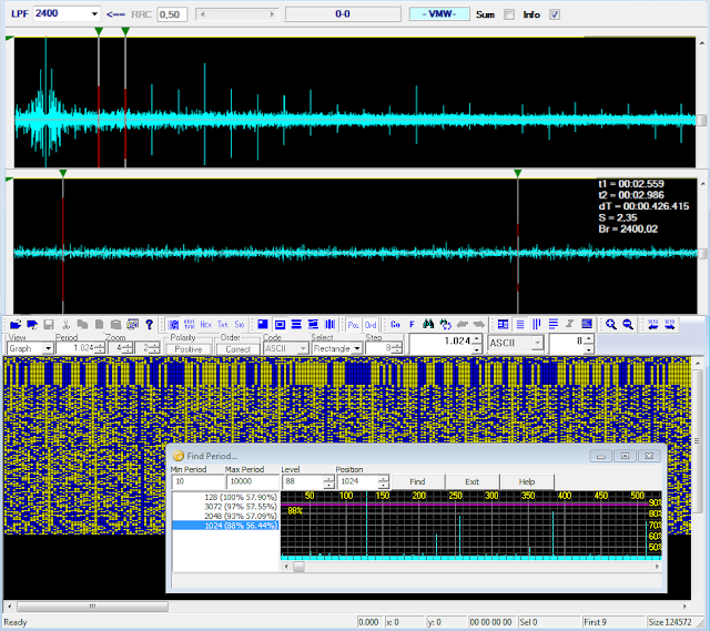
This is my follow-up to an interesting post discussed on the radioscanner.ru forum about a PSK2 transmission of the Chinese Navy and started by my friend KarapuZ [1].  The raw demodulated stream consists of an initial preamble followed by data block consisting of a serie of 16-bit structures which are delimited by solid columns of "1"s or "0"s; the  period is calculated in 3072, 2048, and 1024 bit (128-bit length is due to the preamble sequences): the percentage values in figure 1 indicate respectively  the average ACF value for the given period, followed by the real value of the ACF for that period). Although the value of 1024 bit is the third positive result, both ACF and CCF indicate this as the most likely, being the other two integer multiples of it (x3, x2): this way, the stream consists of 64 "channels", each consisting of 16 bit.

Fig. 1

As noted by my friend Cryptomaster, the 15-bit information between the solid columns is parity-checked; thus, assuming the parity bit is added, as usual, after the data string, each row could consist of 14 bits for data (x) + 1 parity bit (p) + 1 delimiter bit (d): xxxxxxxxxxxxxxpd.
 
I proceeded to the parity check of some channels taking into account all sixteen bits, given that: 
 
* the add of a column of "0"s does not affect the parity checksum of the channel (even or odd); 
* the add of a column of "1"s switches the parity checksum (from even to odd and vice-versa).

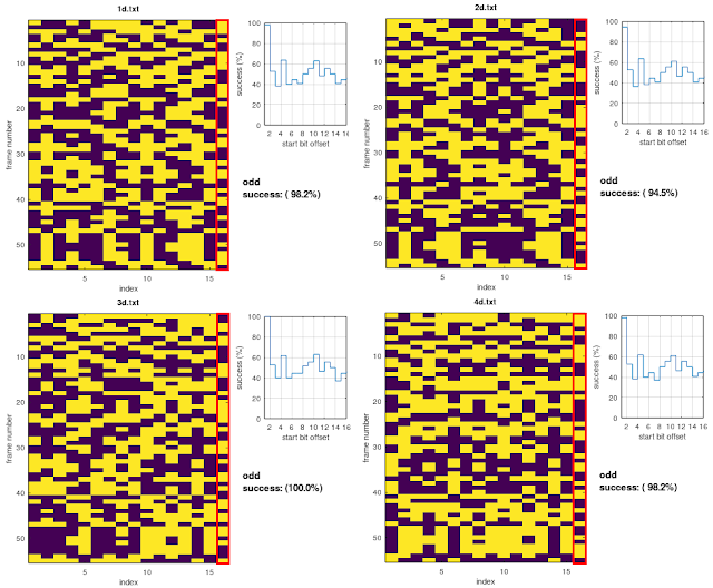
The results for some channels are shown in figure 2, it's to be noticed that the max number of dd/even parity parity matches occurs after shifted the stream (offset >1). Looking at the sequence of the parity checksums of the examined channels, and considering the previous assumptions, we get an apparently random alternation of odd and even parity checksums. 

Fig. 2

After the differential decoding, the channels' "delimiters" disappear, so I tried to get the differential decoding of each channel resorting to some sort of workaround: basically I cut off the 16-bit channels from the plain decoding and then I differential decoded each of them. Yes I know, it's an hazard as it assumes that the channels are individually differential encoded (in real-world the first bit of the n channel depends on the last bit of the n-1 channel) ... however, in that way, the channels are all odd-parity checked and perfectly aligned (figure 3).

Fig. 3 - channels after their individual differential decoding

Since the use of a single parity bit cannot correct any errors, and given the amount of data transmitted, my idea is that they could use a kind of (16,k) coding with the overall parity bit added at the end of the codeword.

For what concerns the preamble sequence, it can be successfully descrambled using the polynomial x^18+x^13+x^11+x^5+x^2+1 (figure 4): it means that the preamble actually consists of a 128-bit pseudo-random sequence (PRBS) which is part of the M-sequence generated by the aforedmentioned polynomial.

Fig. 4 - 128-bit PRBS used as preamble

https://disk.yandex.com/d/b8oQdmhTJcJhPg

[1] http://www.radioscanner.ru/forum/topic40144-14.html#msg1540957