7 March 2016

Chinese-64: MFSK-64, 37.5/18.7 Bd 37.5Hz


Since the weak signal I asked my friend KarapuZ to send me one of his recordings of the Chinese MFSK-64 modem: it's easy to verify that both the records show the same start sequence of symbols (pic. 1).

pic.1
The signal, copied on 16990.2 KHz (cf) around 0910 UTC, consists of 64 tones, 37.5 Hz spaced, modulated alternatively at 37.5 and 18.7 symbols/sec speed (pic. 2 for 37.5 Bd speed).

pic.2
It's worth nothing the characteristic "dual-speed" modulation, seen in both the two recordings: in some segments the speed switches from 37.5 to 18.7 Baud  and conversely (pics 3,4)
pic. 3
pic. 4
The initial part is always modulated at 18.7 Baud and - as said - seems to transport the same data (pic. 5):

pic. 5


https://yadi.sk/d/ZRGpFEoi3A9jkM

3 March 2016

QPSK 1500Bd-19200Bd (Maritime Band)

Thanks to my friend KarapuZ, I recently had the opportunity to play with some signals heard in HF maritime segments, fixed and mobile services, mainly recordered on 8400 and 12300 KHz/USB.
The most of these signals have wide-band high-speed performances (although they do not belong to 188-110C App. D) as the following 19200Bd DQPSK whauch occupies a band of  ~24KHz bandwidth (pic. 1).

pic. 1
As in almost all these signals, a 1500Bd starting block seems used to announce or precede the session. As shown in pic. 2, this block has 1500Bd BPSK modulation in the preamble and trailer segments and 1500Bd QPSK modulation in the data block; the follwing three segments have 19200Bd QPSK modulation (pic. 3).

pic. 2 - 1500Bd starting segment
pic. 3 - 19200Bd segments
By selecting and analyzing the second 19200Bd segment, the longer one, we can get some clues about its frame structure. Looking at pic. 4 we can see frames of alternating data and miniprobe symbols. Each data frame consists of a data block followed by a BPSK mini-probe consisting of symbols of known data.  After 4 data blocks, the initial BPSK preamble (or an its symbol subset) is reinserted most likely to facilitate late acquisition of an ongoing transmission.
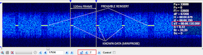
pic. 4 - frame structure
Frame structure and times are confirmed by running both CCF and ACF functions (pic. 5): note that 120ms frame makes 2304 QPSK symbols, ie 4608 bits, at 19200 Baud speed.
 
pic. 5 - CCF and ACF results
In order to find the data block and known data (miniprobe) lengths we need to investigate the 120ms frame by using a bitstream analyzer as shown in pic. 6.
 
pic. 6 - 19200Bd segments
As expected, the period legth is 4608 bits that matches the 120ms or 2304 QPSK symbols. Since the mini-probes consist of well known data, their pattern is easily recognizable into the bitstream and we can get a pretty acurate measurement of the length: 512 bits, ie 256 QPSK symbols (pic. 7)

pic. 7 - known data lenght
Unless my mistakes, each 2304 symbols frame consists of a data block consisting of 2048 data symbols followed by a mini-probe consisting of 256 symbols of known data. After 8192 data symbols, ie each four data blocks, a 584 known symbols set (preamble?) is reinserted (pic. 8) [1]

pic. 8 - frame structure

Little or nothing can be said about the secondary protocol: we can work on just the over-the-air symbols, unless to find the scrambler ploynomial, interelaver lenght and CRC algorithm... but that's another story.

My friend Alipio pointed me to an interesting question: the superframe length and the way to measure it.
We know that the superframe consists of 9544 symbols:

4 data-blocks: 8192 symbols
3 mini-probes: 768 symbols
reinserted-preamble: 584

while Alipio says that the reinserted-preamble is made up by the fourth miniprobe + the preamble itself (as in MS188-110 style):
4 data blocks: 8192 symbols
4 miniprobes: 1024 symbols
1 preamble: 328 symbols

Perhaps it's only a question of interpretation of the fourth mini-probe.
  

[1] MIL-STD 188-110C W/ CHANGE NOTICE-1 (03-JAN-2012) removed the Paragraph D.5.4 sentence "The reinserted preamble facilitates acquisition (or re-acquisition) of an ongoing broadcast transmission." since it refers to a feature that is obsolete.

26 February 2016

A real example of e-mail over HF (via FTP) using STANAG-5066 and MS188-110A

in this recording two stations run STANAG-5066 with BFTP protocol client (a File Transfer Protocol) in order to exchange e-mails using the MS188-110A serial waveform. Note that the E-mail delivery does not happen here using STANAG-5066 HMTP client but rather by FTP_ing the email file (containing all the SMTP headers and fields) ready to be processed by common e-mail clients such as Microsoft Outlook. 
It is worth mentioning that BFTP (Basic File Transfer Protocol) client is defined by  STANAG-5066 Annex F.10.2.2, that same Annex also defines the Compressed File Transfer Protocol client (CFTP) that provides the most bandwidth-efficient exchange of data just using BFTP to send compressed file (see the comment about "MIL-STD-188-141B Notice 1" below at the end of the post).
Talk about e-mail and file-transport protocols go beyond the purpose of the blog so I prefer to have an  HF approach, keeping in mind that STANAG-5066 is designed for running IP applications over HF (STANAG-5066 IP based networks can be thought of as being an HF radio based version of the Internet) and that the stuff, in this sample, is arranged as in pic. 1.


pic.1
As said above, the heard waveform is a standard MS-188-110A serial, as can be verified by SA (pic. 2) although a little shift of the sub-carrier from the nominal 1800 Hz. Since at this stage the signal is coming directly from the USB demodulator, we face Over The Air (OTA) symbols. The structure of the MS188-110 frame is recognizable from the bitstream returned by the SA phase-plane demodulator after its conversion (pic. 3).

pic.2
pic.3 - OTA bitstream after demodulation performed by SA
In order to dig the signal we need de-scramble and de-interleave it and then  remove the extra bits added by the FEC encoder: a basic decoder will do the job returning the bitstream after the MS188-110 removal (pic. 4). 

pic.4 - the bitstream after the MS188-110 removal
Once detected the presence of STANAG-5066 as "secondary" protocol, we need to remove also its encapsulation so to get  the email message that have been transferred by BFTP protocol at sender side. Note that the name of FTP protocol is HBFTP, as it appears in the output window of the analyzer (pic.5). 

pic.5 - the bits trasferred by HBFTP after removed STANAG-5066 and MS188-110A
The acronym HBFTP could stand for HF-BFTP and is suggested to be the Harris implementation of this protocol, available in mail-gateway as the HARRIS RF-6760W Wireless Message Terminal or RF-6750W Wireless Gateway.
The contents of 000_HBFTP--3  can be saved to a file and Windows assigns the .eml extesion since the file exhibits all the features as it was received from a conventional SMTP server via an Internet connection (pic.6).  The file can be  opened and processed by Microsoft Outlook w/out problems: Outlook simply does not care where and how this file has arrived (pic. 7). For reasons of confidentiality the email addresses have been deliberately blackened.

pic.6

pic.7
MIL-STD-188-141B (change notice 1, Appendix E) defines a version of email specially adapted to HF communications. Commands to and from the server are aggregated into blocks to overcome the high latency introduced by HF transmission methods. This greatly improves the efficiency of email when carried over HF.
[...]
E.5.2.1 Compressed file transfer protocol.
The Compressed File Transfer Protocol (CFTP) sends compressed e-mail over an HF link using a file transfer protocol, rather than a mail transfer protocol. Messages produced by an email application are processed by a MTA, compressed in CFTP, segmented in the STANAG 5066 Basic File Transfer Protocol (BFTP), and passed to the subnet interface by the STANAG 5066 Reliable Connection Oriented Protocol (RCOP). At the receiving node, this process is reversed, and the uncompressed e-mail message is delivered to the receiving MTA for delivery or forwarding.
[...]
At this purpose, it is worth noting that the name of the compressed file (.gz extension) produced by CFTP is visible in the non-sense output of the MS188-110A decoder  shown in pic. 8

pic.8
The document "MIL-STD-188-141B Notice 1" can be downloaded from everyspec.com
 

23 February 2016

Ital-HDLC/QUEDRE (High Level Data Link Control)

Looking at the Data Link layer, the many and seemingly boring STANAG-4285 transmissions start to get interesting: the following is an example about the pair S-4285 and HDLC.
The HDLC (High Level Data Link Control) is a group of protocols for transmitting synchronous data packets between Point-to-Point nodes and operates at the data link layer of the OSI reference model. The protocol uses the services of a physical layer (for example STANAG-4285 or MS188-110 waveforms) , and provides either a best effort or reliable communications between the transmitter and receiver (i.e. with acknowledged data transfer as ARQ). The type of service provided depends upon the HDLC mode which is used.
Each piece of data is encapsulated in an HDLC frame (pic. 1) by adding a trailer and a header. The header contains an HDLC address and an HDLC control field. The trailer is found at the end of the frame, and contains a Cyclic Redundancy Check (CRC) which detects any errors which may occur during transmission. The frames are separated by HDLC flag sequences which are transmitted between each frame and whenever there is no data to be transmitted (idle phase).
There is much documentation about it in the web, some links are given at the bottom.
pic. 1 - HDLC Frame Structure showing flags, header 
(address and control), data and trailer (CRC-16)
Sample HDLC data signal follows, when not sending data, a hardware generated idle pattern is present on the data signal:

[... idle pattern ...][Flag][...Data...][CRC][Flag][... idle pattern...]

As said, HDLC can be met in STANAG-4285 and MS188-110 as "secondary" (transported) protocol: the following is an example of its detection just in a STANAG-4285 transmission (pic. 2).

pic. 2 - a common STANAG-4285 transmission as seen by SA
Since I'm investigating the Data Link, I need a bitstream after having de-interleaved and removed the overhead bits added by the underlaying waveform; in other words, I need a STANAG-4285 decoded output. After identifying the correct settings for data-rate and interleaver, 1200bps/short in this case, I ran a k500 session and got the bitstream coming from the upper layer (pic. 3) which I then saved in a ASCII-bits file.

pic. 3 - bistream of that same transmisssion after stanag-4285 removal
The HDLC flags are easily identified looking for the "01111110" sequences (pic. 4) and the "presence" of this protocol has been confirmed (pic.5):

pic. 4
pic. 5
Things work in the same "logical" way TCP/IP stack does: as the data bits (the payload) flows down along a layer (transmitting-phase), they are encapsulated by (one of) the protocol running at that layer and this packet, data and protocol overhead, just forms the payload for the protocol that works at the next  layer. In this sample it's something like:
In the receiving-phase the packets go up the stack and are progressively de-encapsulated in order to return the starting payload, ie.e the original user-data.
That said, after removing Stanag-4285 and then the HDLC stuff, I got the sent messages (pic. 6).

pic. 6 - HDLC messages
Frames are recognized as idle sequences (idle lin) and are characterized by the repetitions of the string "QUEDRE" closed by "XT". Other than the frame type, the bitstream analyzer correctly detects the HDLC blocks, sizes and computes CRC (pic. 7).

pic. 7
The word "QUEDRE" does not belong to the embedded commands of HDLC, rather it seems a sort of an agreed string used for the idle sequences (at least here). That string is anyway one of the distinctive signs, since some bit analyzers tools use indifferently both the terms Ital-QUEDRE and Ital-HDLC just to indicate this feature in respect of the standard HDLC protocol. Difficult to say what QUEDRE means, perhaps a sort of acronym or most likely an agreed term, as said above, but in lack of a safe source these are only speculations. Since there are no (encrypted) messages in the HDCL data fields, these are almost surely some test transmissions.

It is worth noting that the QUEDRE string is clearly visible also in the output of any STANAG-4285 decoders by enabling the synchronous mode with 8N1 framing: probably the decoder will be Data Link aware so you will just see those repetitions and some other garbage due to the HDLC headers, addresses and CRC (pic. 8). Although the output text be consistent, this way is slightly misleading because you lose the knowledge of the Data Link.

pic. 8

http://www.interfacebus.com/HDLC_Protocol_Description.html 
http://www.synclink.com/html/hdlcmode.htm 
http://www.erg.abdn.ac.uk/users/gorry/eg3567/dl-pages/hdlc-framing.html 

19 February 2016

MS188-110B, Appendix C/D scrambler

Both the High Speed Waveforms (HSWF) and Wide Band HF Radio waveforms (WBHF), described first time in the Appendices "C" and "D" from the standard MS188-110B, use the same scrambler. Modems operating over multiple discrete channels (Appendix F) also use this same scrambler since they use the waveforms from Appendix C. The scrambling sequence generator polynomial is:
x^9 + x^4 + 1
and is initialized to 00000001 at the start of each data frame, i.e. each 256 transmitted symbols (data block lenght is the same in both the two waveforms families). The length of the scrambling sequence is 511 bits,  computed as the maximal number of its states excluding the all-zeroes state (2^9 -1). For a 256 symbol data block with 4 bits per symbol, this means that the scrambling sequence will be repeated about 2 times, while for 6 bits per symbol just slightly more than 3 times, although in terms of symbols there will be no repetition (pseudo-random generator). In other words, the scrambler is designed to not have auto-correlation property, contrary to what happens for the MS188-110A scrambler, as we saw here, where the scrambler produces a periodic pattern 160 transmit symbols (480 bits, since the PSK-8 modulation) in length that at certain data rate speeds affects the value of ACF. 
I do not want reinvent the wheel here but only practice of analysis, so I just looked for a confirmation of this behavior (and described below) by analyzing the bitstream produced by a software-scrambler that I wrote in Lua language for both PSK-8 and QAM-16 modulations, in the latter case I also examined a real-world QAM-16 signal to verify the lack of possible signs/repetitions caused by the scrambler.

PSK-8 modulation
For PSK-8 data symbols (3200 bps and 4800 bps), the scrambling shall be carried out taking the modulo 8 sum of the numerical value of the binary triplet consisting of the last (rightmost) three bits in the shift register, and the symbol number.  A block diagram of the scrambling sequence generator is shown in pic. 1, in this illustration, three output bits are shown: this is the case for PSK waveforms.

Pic. 1
After each data symbol is scrambled, the generator shall be iterated (shifted) the required number of times to produce all new bits for use in scrambling the next symbol, so will be 3 iterations for PSK-8. Since the generator is iterated after the bits are use, the first data symbol of every data block (256 symbols) shall, therefore, be scrambled by the appropriate number of bits from the initialization value of 00000001.

pic. 2
The sw-scrambler writes the scrambled symbols, ready to be sent to the PSK modulator, to the "scrambler-output.txt" file. Examining this bitstream (pic. 2) a 768 bits period is revealed and this lenght is exactly the lenght of the 256 PSK-8 symbols data block: there is no evidence of 511 bits cycle due to the scrambler.

QAM-16 modulation
The data symbols for QAM modulations shall be scrambled by using an exclusive or (XOR) operation: sequentially, the data bits forming each symbol (4 for QAM-16, 5 for QAM-32, 6 for QAM-64 and 8 for QAM-256) shall be XORed with an equal number of bits from the scrambling sequence (pic. 3).

pic. 3 - scrambler for QAM-16 modulation
After each data symbol is scrambled, the generator shall be iterated 4 times to produce all new bits for use in scrambling the next symbol. As said, since the generator is iterated after the bits are use, the first data symbol of every data frame shall, therefore, be scrambled by the appropriate number of bits from the initialization value of 00000001. I used a constant data symbol value (0110) just to highlight the behavior of the scrambler.

pic. 4 - running the sw-scrambler for QAM-16 modulation
The sw-scrambler writes the scrambled symbols to the "QAM-16-scrambler-output.txt" file. Examining this 5000 symbols bitstream (pic. 5) a 1024 bits period is revealed. As in the case of PSK-8 scrambler, this lenght is exactly the lenght of the 256 QAM-16 symbols data block: also in this case there is no evidence of 511 bits cycle due to the scrambler.

pic. 5
real-world QAM-16 signal

pic. 6a - real-world MS188-110C App.D signal

pic. 6b - MS188-110C App.D, QAM-16 ACF
As expected, the ACF returns a 120ms period (pic. 6) that makes 288 symbols length frame at 2400 Baud. Since the data block for QAM-16 modulation is always 256 symbols, it follows that mini-probes are 32 symbols lenght (waveform n.8 from Appendix D TABLE D- XI):


After demodulating the QAM-16 signal with SA, it was then converted into an ASCII-bit file by using a simple HEX2BIN converter also written in Lua: the output file was then analyzed using a bit-flow processor tool. 
The analysis of the bitstream reveals a strong 1152 bits period that is exactly what is expected for the 4-bits symbols WBHF waveform (pic.7):

pic. 7
data-block: 256 symbols = 1024 bits
mini-probe: 32 symbols = 128 bits
frame (data-block + mini-probe): 288 symbols = 1152 bits
and in terms of symbols, there are no repetition caused by the scrambler (no auto-correlation property).

The same scrambling sequence generator polynomial x^9 + x^4 + 1 is also used in STANAG-4285 waveform (see Annex-A to STANAG-4285) but with a different inizialization vector (see the picture below and pic. 1):
and the results are obviously the same, the bit flow processor only detects the expected 768 bits period: