25 February 2022

STANAG-5066 over MIL 188-110A: SK AF messaging

Slovakian AF communications spotted on Monday at 6343.0 KHz/usb, rather unusual frequency given the previous logs (actually first time heard on this qrg) and no more heard since last monday 21. The usual paradigm is used: ie, 188-141 2G-ALE handshake (S1L caller, P10 called) that is followed by the data forward by means of 188-110A ST modem and STANAG-5066 as datalink protocol.

Fig. 1 - STANAG-5066 bitstream

No transport protocol is used since STANAG-5066 assumes the burden of message integrity within the HF network: indeed, the email file are compressed and then transferred from one SMTP server to another by using HBFTP (Basic File Transfer Protocol) as per Annex F of STANAG-5066. BFTP implements a very simple end-to-end file transfer protocol based on the ZMODEM protocol and shall be provided by STANAG-5066 implementations: in this case, the initial "H" could stand for Harris implementation. It's to be noticed that BFTP is connected to the RCOP (Reliable-Connection-Oriented Protocol) socket interface.
HSMTP (likely Harris SMTP, Simple Mail Transfer Protocol) routing shows that the recipient node is at 1-hop distance (DP and NP values).
The email addresses and other terms reveal that the messaging system software, and most likely the connected radios, are provided by Harris Corporation, almost surely the Harris RF-67x0W Wireless Gateway suite. 

Fig. 2

about users:
ALE callsign P10 (Stanag-5066 address: 10.000.000.005) is "prezovvzs", Prezov VzS
ALE callsign S1L(Stanag-5066 address: 10.000.000.004) is "sliacvzs", Sliac VzS  
("Vzdušné Sily" is the Slovakian for Air Force)
It must be noted that for "domestic" traffic they do not use their S-5066 Regional Assignee range 6.42.y.z but rather 10.x.y.z.
Also interesting is the use of ESET Smart Security, database version 8756 (20130902), to protect the systems against virus and malware. 

https://disk.yandex.com/d/5kVfxb1Y95_R2Q

17 February 2022

5N1 frames To 112-bit period stream (just for fun, again)

This post is the follow up, and the counterpart, of the previous one (112-bit T stream To 5N1 frames, just read it for background). If while receiving we need a "downsampling" by a factor of 16 of the 112-bit period stream coming from the modem, when transmitting we have to expand the source 5N1 frames bitwise by the same factor before to forward them to the modem. As in the "downsampler", I used the multiplexer/demultiplexer module CD74HC4067 and two I2C connected Arduino boards.

Each bit of the 5N1 frames is spread to a 16-bit D-type latch register which is three-state connected to the 16-input of the multiplexer, the inputs are then selected and forwarded to the multiplexer serial output at a speed that is 16 times faster than the 5N1 frames (figs. 1,2).

This way each input bit is 16 times repeated in the serial output and thus the stuf performs the 16x expanding. Not having a 16-bit register at home, I used two 74HC595 (8-bit, serial-in, parallel-out shift register that feeds an 8-bit D-type register).
 
Fig.1 

Fig. 2

The 5N1-112 conversion is not done via software: a board takes care of sending data to the other one which forwards 'em and manages the ICs. Input/output data are dispalyed on the serial ports (COM3 on the sender, COM4 on the receive expander, see figure 3 below).

Fig. 3

As already mentioned in the cited post, I do not  aim to "replicate" the circuit used to perform the 5N1-112 conversion but only try to simulate its operation through the use of a multiplexer. For those interested in playing with the two circuits (...but I really don't think so) the 4 rough "sketches" can be downloaded from here along with the data sheets of the used ICs:   
https://disk.yandex.com/d/SVTcXiikai1VRQ 

11 February 2022

112-bit period stream To 5N1 frames (just for fun)

I recently re-thinked to the odd 112-bit period stream sent by UK MoD via STANAG-4285 and described  here, more than anything else I was intrigued by the "stuff" used for the manipulation of the streams. Looking at the bitstream of figure 1, one can see that either the sync sequence and the Initialization Vectors are 16 times bitwise expanded, thus that "stuff" shall sit in the middle between the crypto device and the STANAG-4285 modem, assuming that it is not embedded or implemented in one of the two devices. 

Fig. 1

During the receive phase it shall perform a downsampling of the received 112-bit period stream by a factor of 16 while in the transmit phase it will expand the source 5N1 frames bitwise by the same factor: in a few words, in some way the stuff acts like a multiplexer/demultiplexer (figure 2).

Given that:
Z = serial input/output 
Yn = input/output channels

Tx side (expander):
each input bit is applied to all the input channels and their selection speed is 16x the speed of the input bits, ie:
bit 00 → Y0,Y1,Y2,...,Y15 → Z
bit 01 → Y0,Y1,Y2,...,Y15 → Z
...
bit 15 → Y0,Y1,Y2,...,Y15 → Z

this way each input bit is 16 times transferred into the serial output and thus performing the 16x expander.

Rx side (downsampler):
The selection of the output channels is in sync with the input bits (same speed), ie:
bit 00 → Y0
bit 01 → Y1
...
bit 15 → Y15

since all the sixteen bits have the same value (1 or 0), it turns out that draining the output only from Y0 (or from any other single channel) we get the needed downsampling by 16.

Fig. 2

I started thinking about how that "stuff" could be implemented: software or wired-logic solution. The software solution is easy to code and may be based on a PC as well as on Single Board Computers such as Raspberry Pi or Banana Pi or also on microcontrollers as Arduino, obviously the serial interfaces are needed. Just as a Proof of Concept, and  to have some fun, I decided to to demonstrate the wired-logic feasibility with multiplexer/demultiplexer breakout board module CD74HC4067 and two Arduino boards connected via I2C communication bus in the Master-Slave configuration (1). 
 
In the downsampler Rx configuration (figure 3), one Arduino board ("Uno") acts as Slave and it's requested to send the 112-bit period stream, this board represents the output of the S4285 modem; the second Arduino board ("Mega2560") is the master and drives the dmux CD74HC4067:
• requests data to the slave and forwards them to the dmux serial input 
• selects the output channel Yn through the address bus S0-S3
• withdraws the Y0 output and forwards it to a LED (ie the following crypto device)
The master board also controls the HD44780 LCD which is added to display the received 5N1 frames after their downsampling ...almost useless since data are dispalyed on the serial ports (COM3 on the sender, COM4 on the receiver: see figure 5).
 
 
Fig. 3 - Downsamnpler Rx connections


Fig. 4 - downsampler at work

Fig. 5 - serial port monitor of sender (COM3) and dowsampler (COM4)

As aforementioned, this post is not intended to build the conversion circuit 112-5N1 but to simulate its operation through the use of a simple demultiplexer ... and to have some fun. In a next post I will also try the reverse operation 5N1-112 but always using the module CD74HC4067 this time as a multiplexer. By the way, I used the CD74HC4067 as it can be used both as a multiplexer and as a demultiplexer, in this circuit it can be replaced with the SN74154 (dmux only).  


(1) The I2C communication bus is very popular and broadly used by many electronic devices because it can be easily implemented in many electronic designs which require communication between a master and multiple slave devices or even multiple master devices. The easy implementations comes with the fact that only two wires are required for communication. The two wires, or lines are called Serial Clock (SCL) and Serial Data (SDA).  The SCL line is the clock signal which synchronize the data transfer between the devices on the I2C bus and it’s generated by the master device. The other line is the SDA line which carries the data.

7 February 2022

IoT on HF NVIS (tentative)

 I56578, ANgazu

The Antarctica department of La Salle Campus, Ramon Llull University of Barcelona has been carrying out studies for some years, among which we are interested in the communications part. They study remote sensing IoT communications using NVIS platforms, a very useful system in places where there are no mobile communications infrastructures and the physical conditions do not invite useless movements. They are also studying HF links between Antarctica and Spain, of just over 12000 km. To allow the sending of the appropriate sensor data, since many bases remain closed or under minimum during the Antarctic winter. These tests include testing with various modulations to try to find the optimal one for the application.
Regarding the tests in Spain. they use an NVIS link between the Barcelona campus and the Cambrils campus. As far as we know, they do the tests at 5400 KHz, taking advantage of the University's Radioclub that collaborates with the department.
At present, we guess they continue with the tests and we assume that the recordings we are making correspond to them. The use of NVIS antennas limits the reception possibilities, since the Alicante KiwiSDR is not operational. However, with the available devices we are recording signals and we hope that some of them will meet the necessary quality for their analysis.
We can see in the spectrogram (figure 1) that they use a bandwidth of about 12 Khz, a bit excessive for the signal parameters. 

 
Fig. 1

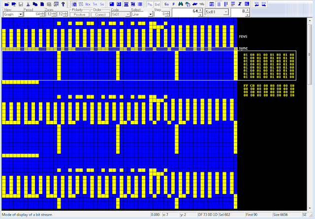
The blocks are transmitted between 1 and several minutes apart. There does not seem to be a regular structure. Every block is made up of 25 segments, although there are some 14 and 50. Each segment measures about 265 ms, of which 60 correspond to a continuous carrier that is about 600 Hz. above the transmitter carrier.

Fig. 2

The "current" framing of the segments is very different than the one described/used in 2018, see figures 3a-3b: its duration is 265ms and in my opinion the data part has a duration of 70ms and is followed by a 115ms (or better, 110ms + 5ms) pattern. 

Fig. 3a - current framing (the one we recently saw)

Fig. 3b - framing used in the tests carried out in 2018

Although there are some uncertainties and doubts in some segments the modulation used appears to be PSK4, but its analysis requires much more attention: at this regard I edited the signal and removed to 60ms tone as well as the ending 115ms segment (see figure 3a). Results are shown below, please note that the SA PSKn demodulator:
* does not lock on any sync sequence thus phase rotations are unavoidable
* it uses the following symbol mapping for PSK4 constellation:
0 (00) ==>  00°
1 (01) ==>  90°
2 (10) ==> 180°
3 (11) ==> -90°

Figures 4a-4b shows a standard PSK4 constellation with its regular and expected transitions between the four states, anyway figure 4c shows that the trajectories do not match the ones of PSK4 (figure 4d): ie, all the transitions are featured by zero-crossing paths like a π/2 rotated PSK2 (0<->180,90<->-90). Also note the slight "smudges" on the trajectories of figure 4c which led us to analyze the states by using a 8-ary constellation.

Fig. 4

Actually, we don't know how much sense an 8-ary constellation makes, since the modulation clearly "dances" around four states, anyway it's interesting to see the π/4 rotation of the transitions shown in figure 5b as verified by the trajectories shown in figures 5c,5d.

Fig. 5

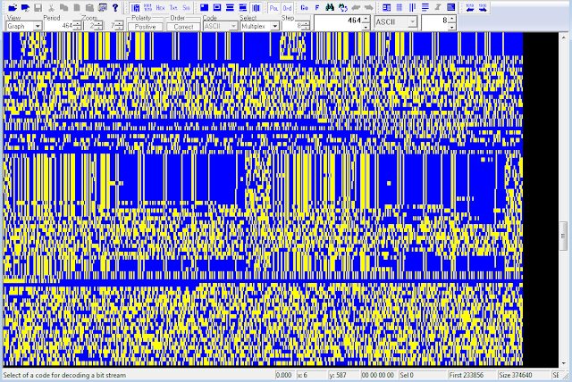
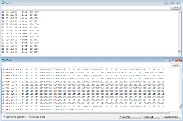
That said, we demodulated the blocks using PSK4 demodulator and the mapping shown above: the resulting bitstream is about 914 bit (457 dibit symbols) which is compatible with duration & speed (205ms @2380Bd) of the bursts. At glance, it seems that each segment of a block transports the same data (figure 6).

Fig. 6

That's all at the moment, further recordings and analysis are obviously needed and hopefully some confirmation from the testers. Comments and tips are very welcome.

https://disk.yandex.com/d/qmm7aDnwWshq0w

3 February 2022

a curious STANAG-4285 transmission

Really curious STANAG-4285 transmission sent me by my friend IK1YDE Andrea who was the first to spot and analyze the signal. The oddity is that, after S4285 demodulation, the Initialization Vectors, as well as being repeated within each message, consist of the unique(!) and a bit "basic" sequence: 0x0001000100010001 (see figure below).
Actually, KG-84/KIV-7 devices use 2 x 128-bit sequences as IV and these sequences - as well as in other crypto devices - change with each new message, even if the same message is repeated (in this case 0xFFC00000000000000000000000000000).  

Fig. 1
 
Andrea heard that transmissions on 4165.6 KHz/USB, the only (Freq/Mode) match I found dates back to 2005 and refers to French-Ny FUE. No other interception in recent days, even if sporadically monitored.  No idea what this transmission is, maybe tests of new setup?