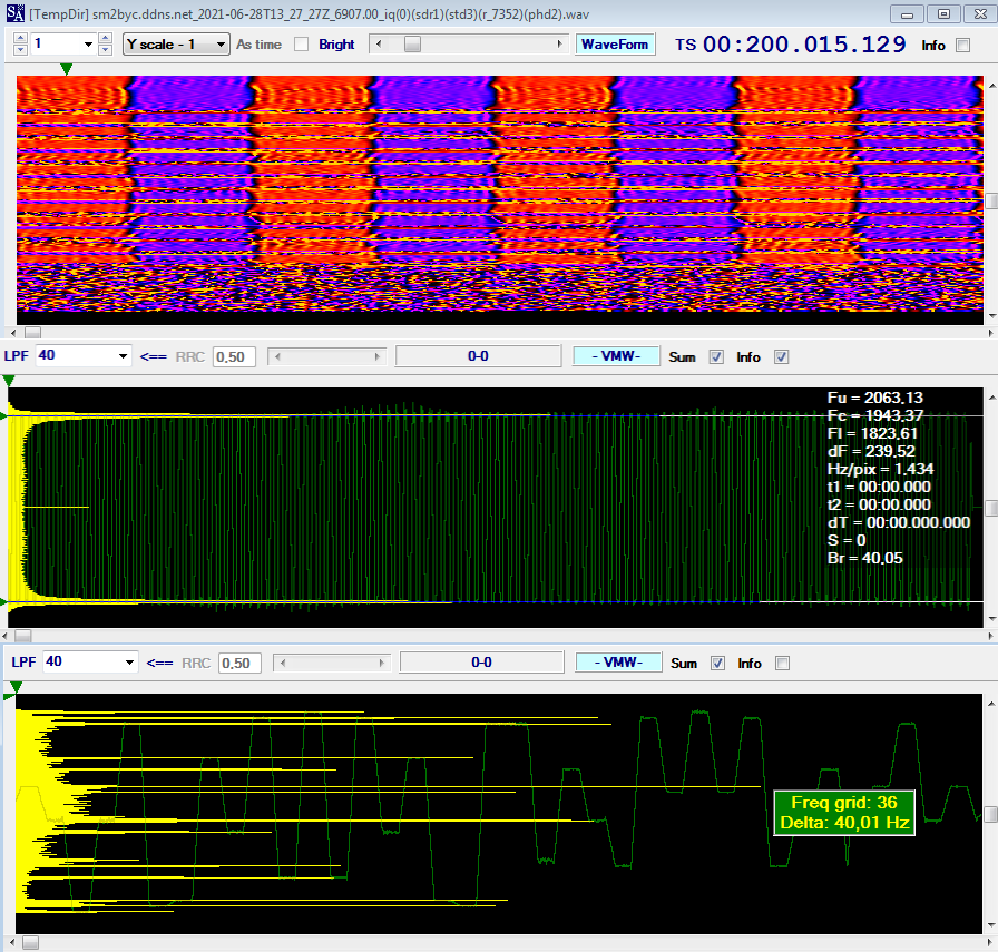
6907.0 KHz (cf): unid SELCAL waveform spotted on 6907.0 KHz (cf),. The waveform consists of 40Bd/240 FSK idling part followed by MFSK-36 40Bd/40 (likely the Id of called station).
 | |
| Fig. 1 |
 |
| Fig. 2 |
https://disk.yandex.com/d/XlHhceBC9fLlvQ
6907.0 KHz (cf): unid SELCAL waveform spotted on 6907.0 KHz (cf),. The waveform consists of 40Bd/240 FSK idling part followed by MFSK-36 40Bd/40 (likely the Id of called station).
| |
| Fig. 1 |
|
| Fig. 2 |

From 19 to 23 June I monitored interesting transmissions on 5091.5 KHz/USB that seem to use a kind of "combined" waveform which consists of FLSU BW5 waveform followed by 188-110A 300bps waveform. For what concerns the timing, the sendings occur each minute, they last about 31 seconds and are arranged in a way that resembles the circuit mode service of STANAG-4538. Starting from thursday 24, these broadcasts have not been repeated (at least until today).
 | |||||
| Fig. 1 - ACFs |
As said, it seems that the data are sent using a transmission composed of two parts: a sequence of FLSU PDUs, which are transmitted using the BW5 burst waveform, and the payload data, transmitted using the 188-110A serial waveform. These two parts are transmitted contiguously with no dead time separating them (Figure 2).
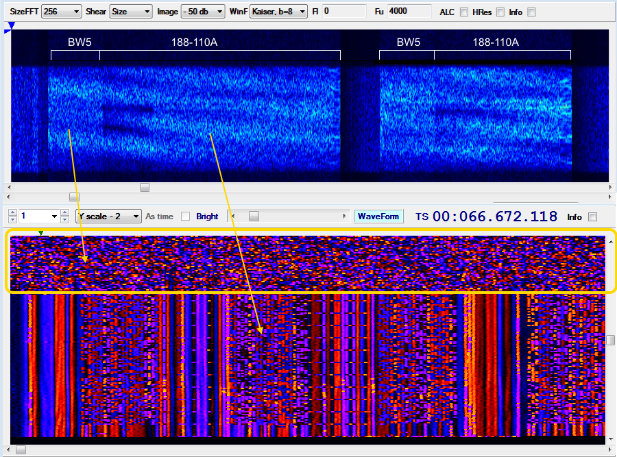 |
| Fig. 2 - framing |
That kind of waveform (BW5 + 110A) is indeed very odd, unless I have
been mistaken and it is an overlapping of two distinct transmissions...
but it would still odd that the overlapping be so perfect and continuous
for more than two days. Anyway, if it's a real "combined" waveform then it's definitely a synthesized waveform (SDR).
For clarity - however - it must be said that:
a) BW5 waveform (and thus the FLSU protocol) has been detected by the examination of the signal's ACF and its payload;
b) the length (duration) of the initial BW5 sequence finds a clarification in this post;
c) BW5 waveform could also be used to transport other types of PDUs and not only the PDUs of the FSLU protocol.
data link protocol
The used data link protocol is also interesting: its initial structure consists of 32-bit (4 bytes) patterns which are common to all the payloads (Fig. 3):
192-bit idle sequences of reversals (alternating sequences of '0's and '1's)
10001011010001111000010010000111 (0xD1E221E1) sequence #1
01111011101101001011100010000111 (0xDE2D1DE1) sequence #2
11 bytes length data block
10001011010001111000010010000111
10001011010001111000010010000111
10001011010001111000010010000111 (5 x sequence #1)
10001011010001111000010010000111
10001011010001111000010010000111
(data block follows)
 |
| Fig. 3 - data link protocol after 188-110A removal |
The two 4-byte sequences are not originated by polynomials and are likely used as sync patterns, although the five repetitions of the sequence #1 lead to think to an Initialization Vector; in my opinion, a such method could be risky in terms of security since the same IV sequence is used for all the forwarded messages (unless they are test transmissions and/or pseudo random traffic). Data blocks seem anyway encrypted.
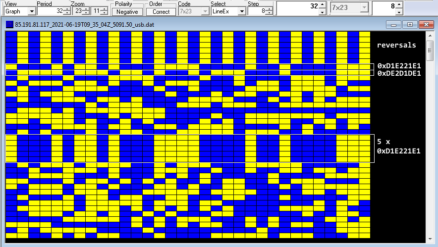 |
| Fig. 4 - details of the 32-bit structure of the data link protocol |
The exact same structure and 32-bit sequences have already been detected in some recordings of 2018 (!): also in this case they were "plain" 188-110A transmissions forwarded in circuit mode service [4].
TDoA direction finding
The transmissions are fairly receivable only in the northern regions of Europe, more precisely I used KiwiSDRs in Norway and Denmark [1][2]: that's a sign that a low power transmitter is used or that they serve a local area. Just about the site of the transmitter, all my direction findings point to a well-restricted area north from Oslo, Norway (Figure 5).
 |
| Fig. 5 - TDoA results |
Norway has released an interactive map of all the military locations where it is forbidden to operate a drone [3]. All the markers indicate an area where it is illegal to take aerial photographs or video using a camera or any other type of sensors: in figure 6 I have cut out an area that more or less follows the area identified by the DF.
 |
| Fig. 6 |
remarks
Starting from June 22 the transmissions show a paradigm change,
a bit more in line with the circuit service model of STANAG-4538: the
structure of the used data-link protocol, anyway, remains unchanged.
These transmissions raise several questions, the first being whether or not it is an experimental combined waveform (and therefore if they are test transmissions). It would also be interesting to identify the transmitter site with greater precision and - if anything - which data protocol is used.
https://disk.yandex.com/d/2I0bzM2nDShWGA
https://disk.yandex.com/d/kD-9y_TFkZoFqQ
https://disk.yandex.com/d/Bt2pIPxE-o6Udw
[1] LB3J SDR in Smøla, Norway http://77.223.174.203:8073/
[2] KiwiSDR by OZ1BFM in Vejby, DENMARK http://oz1bfm.proxy.kiwisdr.com:8073
[3] http://googlemapsmania.blogspot.com/2018/09/norways-secret-military-sites.html
[4] https://i56578-swl.blogspot.com/2018/03/unid-32-bit-secondary-protocol.html
Heard 75Bd/850 FSK transmissions (broadcasts?) on 6372.0 KHz CF until sunday 13th June, no transmission in the following days (at least until today). Transmissions were KW-46 secured and sourced most likely from Barford St.John USAF transmitter. Think of a temporary activation on the occasion of the G7 summit just in UK... is that too imaginative?
 |
| Fig. 1 |
 |
| Fig. 2 |
It happened by chance to analyze a complete session of data exchange in MAHRS mode (ALE + traffic) while I had a STANAG-4285 decoder in active state on the desktop: to my surprise the decoder started printing out a bitstream though - as said - it was set for STANAG-4285 (Figure 1)
 | |
| Fig. 1 |
The first thing that stands out is the equality of the ACF values, Figure 2: 106.6 ms, or 256 symbols. Thus - in my opinion - it seems that the decoder in question (Sorcerer and therefore also K500) tries to identify a signal by analyzing its ACF: probably those kind of decoders have an internal table that allows this association.
 |
| Fig. 2 - ACF values for STANAG-4285 and Echotel serial |
The structure of the frames is anyway very different, unless the first 80-symbol preamble which is common to both the waveforms (Figure 3): S-4285 framing consists of an initial 80 symbol preamble followed by 4x32-symbols data segments and 3x16-symbol probes; Echotel framing consists of the initial 80 symbol preamble that is followed by a data block consisting of 176 data symbols.
 |
| Fig. 3 - framing structure for STANAG-4285 and Echotel |
As third common feature, both the 80-symbol preambles are modulated using BPSK: the pronounced BPSK states in the constellation plane of the Echotel 1810 signal are quite eloquent (Figure 4)
 | |
| Fig. 4 |
STANAG-4285 is not an autobaud waveform so the decoding is based on the user settings, just for fun I played with some sub-modes even if - as obvious - the decoder can't find the expected known symbols (16-symbol probes). The best results, in terms of "confidence", were obtained by setting the bit rate to 2400 bps, obviously the corrections are equal to zero in the uncoded mode:

It must be said that this Echotel 1810 waveform is not the only S4285-like waveform, another example is the 2400Bd PSK-8 serial waveform from the THALES TRC-1752 modem (Thales Système 3000 family), although the latter is more properly defined as "variant".
 |
| Fig. 5 - THALES TRC-1752 STANAG-4285 variant |
At the end, do not blindly trust decoders: they are not infallible and there is no magic wand; just open your wav files and analyze them.
Three new fleet broadcast channels spotted in these days, all STANAG-4481F:
4987.0 KHz (cf) 50Bd from NSS Davidsonville
7455,5 KHz (cf) 75Bd from NSY Niscemi
7457.0 KHz (cf) 50Bd from NAU Isabela
All the the broadcast are KW-46 secured(!), although 75Bd/850 usually run KIV-7/KG-84 devices.


These and other recent catches seem to confirm a change in some transmission frequencies, mostly of 2000 Hz or , even stranger, of 1300 Hz. "There is currently a Navy exercise in progress off the east coast, so the shift may perhaps be supporting that effort or maybe to avoid interference or harmonics on other services at the sites", my friend Mike mco say.
I have updated the page related to the BRASS STANAG-4481F page, it is even more evident that all the transmissions that use the waveform 50Bd / 850 are protected with KW-46.
https://disk.yandex.com/d/XJVGUnkI4D4etg
MIL 188-110A, unlike other waveforms such as STANAG-4539 or STANAG-4285, does not always show the same ACF value as the data rate changes: it is mainly due to the variations of the frame structure (Table XIX) and the way it interacts with the length of the scrambling sequence. The corresponding periods lengths of the bit streams then make it possible to identify the interleaved block boundaries which in turn depend on the bit rate and the interleave delay (Long or Short).
 |
| Fig. 1 - 188-110A Serial Tone blocks |
Table X lists the interleaver matrix dimensions (rows and columns) that shall be allocated for each required bit rate and interleave delay.

The bits obtained from the interleaver matrix are grouped together as one-, two-, or three-bit entities that will be referred to as "channel symbols" (or - more simply - "symbols"): the number of bits that must be fetched per symbol is a function of the bit rate.
The scrambler is feed with a number from 0 to 7 supplied by the data sequence randomizing generator, a 12 bit shift register with the initial state 101110101101 (0xBAD, hexadecimal). After 160 transmit symbols, the shift register is reset to 0xBAD and this sequence produces a periodic pattern 160 symbols in length.
The interleaved blocks boundaries can be identified by looking carefully at the probes in the demodulated bit streams. As per MIL-STD 188-110: during the periods where known (channel probe) symbols are to be transmitted, the channel symbol formation output shall be set to 0 (000) except for the two known symbol patterns preceding the transmission of each new interleaved block. When those two known symbol patterns are transmitted, the 16 tribit symbols are set to Dl and D2, respectively, as defined in table XV and table XVII.

2400 bps
Each data frame has a length of 48 symbols and consists of a data block consisting of 32 data symbols, followed by a probe consisting of 16 symbols of known data. Although the expected ACF is 20 ms, the actual value is 200 ms ie corresponding to a block of 10 frames (Figure 2). Since 10 frames contain 10×16 = 160 probe symbols, the 200ms ACF spikes are likely due to a kind of "resonance" between the 160 probe symbols and the 160 symbols of the scrambing sequence.
 |
| Fig. 2 - 200 ms ACF for 110A 2400 bps |
The short interleaver matrix for 2400 bps consists of 40 rows and 72 columns, ie a length of 2880 bit: that means that 960 tribit symbols will be fetched and transmitted as 30 data blocks (960:32); thus, one interlever block needs 30 frames to be transmitted. As you may see in Figure 3, each three rows the patterns of the last two probes exhibit a discontinuity that is not present in the other probes: that's what we were looking for. Indeed - as seen abvove - 3 period rows contain 3×10 = 30 frames that just identify a single short interleaved block for the 2400 bps speed. The interleaver matrix is fetched in 600 ms, ie 200 ms × 3.
 |
| Fig. 3 - 2400 bps Short interleaver |
A similar calculation can be verified for the long interleaver. In this case the interleaver matrix consists of 40 rows and 576 columns, ie a length of 23040 bit or 7680 tribit channel symbols. Since the 32 symbols length frame, one long interleaved block will be sent into 7680:32 = 240 frames, thus 24 rows (Figure 4). The interleaver matrix is fetched in 4.8 s, ie 200 ms × 24.
 |
| Fig. 4 - 2400 bps Long interleaver |
1200 bps
In case of low data rates (from 150 up to 1200 bps) the data frames are structured as a 40-symbol pattern: each frame consisting of a data block consisting of 20 data symbols, followed by a probe consisting of 20 symbols of known data. The expected ACF value is then 16.67 ms, but the actual one is 66.67 ms ie four times greather (Figure 5). The reason is that four groups of the pairs data + probe count 160 symbols (4×40) and they are just "in sync" with the scrambler length (160 symbols) causing the strong 66.67 ms ACF spikes of Figure 5.
 |
| Fig. 5 - 66.67 ms ACF for 110A 1200 bps |
The short interleaver matrix consists of 40 rows and 36 columns, ie a length of 1440 bit: that means that 720 dibit symbols will be fetched and transmitted as 36 data blocks (720:20); thus, one interlever block needs 36 frames to be transmitted. Nine period rows are indeed the boundary of a single short interleaved block (Figure 6).
 |
| Fig. 6 - 1200 bps Short interleaver |
The long interleaver matrix consists of 40 rows and 288 columns, ie a length of 5760 dibit symbols that will be fetched and transmitted as 288 data blocks (5760:20); thus, 288:4 = 72 period rows is the boundary of each long interleaved block (Figure 7).
 |
| Fig. 7 - 1200 bps Long interleaver |
600-150 bps
The short interleaver matrix for 600-150 bps consists of 40 rows and 18 columns. Given that only one-bit per channel symbol is fetched, a single short interleaved block will be trasmitted as (40×18):20 = 36 frames. The boundaries of the short interleaved blocks are clearly visible each 9 rows in the usual 480-bit/4-frame period (Figure 8).
 |
| Fig. 8 - 600-150 bps Short interleaver |
The long interleaver matrix for 600-150 bps consists of 40 rows and 144 columns. Given that only one-bit per channel symbol is fetched, a single long interleaved block will be trasmitted as (40×144):20 = 288 frames. By grouping the bit stream in a 8-frame period, the boundaries of the long interleaved blocks are clearly visible each 36 rows (Figure 9).
 |
| Fig. 9 - 600-150 bps Long interleaver |
I was just monitoring some interesting sequences of 2400Bd PSK bursts occupying 3 out of 6 channels (each 3 KHz width) according to alternate timings of 40 and 20 seconds: frequencies 5742.5, 5748.5, and 5757.5 (all USB). The 119.6 ms ACF value corresponds to a framing of 287 symbols @2400Bd, ie the waveform STANAG-4539: more precisely, according to its self-identifying feature, a 32QAM modulation at 8000bps speed (Figure 1).
 |
| Fig. 1 - STANAG-4539 framing structure |
Unfortunately, I was not able to get the expected 32QAM constellation but only few states of the outer 32QAM ring (Figure 2).
 |
| Fig. 2 |
I was a bit puzzled until I realized I was seeing an already known signal, more precisely the UK MoD 12800 bps 64QAM bursts [1]: the signals were just badly-tuned (300 Hz frequency offset).
A question arose almost immediately: why, despite the out-of-tuning, the signals are recognized as a 32QAM/8000bps modulation with a sub-carrier error of only 0.2 Hz? I thought about a decoder error, but examining the 103 preamble' symbols that carry information regarding the data rate and interleaver settings, I found that those are actually different in the two cases of 5757.20 and 5757.50 Hz (Figure 3).
 |
| Fig. 3 - data rate and interleaver settings |
I repeated the measurements of modulation and speed using other tuning frequencies, results are in the table below. Notice the discrepancies between the tuning frequency and the error detected by the decoder, expecially in 5757.20 and 5757.50 cases where the signal seems to be exactly tuned:

According to SATANAG-4539 #2.1, the accuracy of the sub-carrier frequency shall be 3×10^-5, ie a max tollerance of ±172 Hz @5,757 MHz is allowed: probably the autobaud feature fails since that kind of "symbols distortion"?
Assuming 64QAM/12800bps as the actual mode (as already assumed at the time), I tried to demodulate a same single burst using two different decoders (say A and B, without naming them). The expected length of the bitstream will be:
13 frames × 256 = 3328 symbols × 6 = 19968 bit
 |
| Fig. 4 |
 |
| Fig. 5 |
5716.0 KHz (cf): STANAG-4481F (apparently) 75Bd fleet broadcast from NAU Isabela (PTR), running with the "odd" and already observerd 3-bit format (Figure 1).
 |
| Fig. 1 |
Removing the third column which contains the replicated bits and then reshaping the resulting bitstream to a 7-bit pattern, it turns out the actual 50Bd speed and the usual KW-46/KIV-7 encrypted stream (Figure 2).
 |
| Fig. 2 |
STANAG-4481 PSK (4481-P) waveform carrying the KW-46 secured fleet broadcast of the Canada's East Coast Navy. STANAG-4481P is basically a STANAG-4285 sub-mode which adopts fixed 300 bps data-rate and long interleaving. As well as 4285, 4481-P is mostly used in NATO Naval broadcast due to its repeated preamble for which it's easy to maintain sync during long transmissions.
 |
| Fig. 1 |
 |
| Fig. 2 - x^31+x^3+1 m-sequence used to sync the receive KW-46 unit |
Transmitter site is most likely the Naval radio Station (NRS) of Newport Corner (NS). Both the NRS Newport Corner transmitter and NRS Mill Cove receivers were automated and are currently operated by HMCS Trinity at CFB Halifax [1].

Fig. 3 - TDoA results
https://disk.yandex.com/d/aksB6d-IgB1n1Q
Cleaning up one of my hard disks I came across an old recording (year 2014) that had no comment file associated with it, so I decided to take a look at it and see what exactly it was. The recording consists of different length bursts, each burst is modulated with PSK2 at a symbol rate of 1200Bd: nothing particularly interesting unless its ACF and, consequently, its period. Indeed, the ACF results in 373.74 ms (Figure 1) that make a length of the period of 448.5 bit (PSK2 @1200Bd), but after the differential decoding the bitstream shows a 897 bit length period, ie just the double of the value obtained using the phase detector.
 |
| Fig. 1 - 373.74ms ACF corresponding to a 448.5 bit length period |
As you know, a such situation is typical in asynchronous framings that have the stop-bit of 1.5 or 2.5 in length: for example, in case of a 5N1.5 framing the bit editor groups two 7.5 bit frames into a single 15 bit pattern because it can't represents a length of half bit. That's just what may happen here: the bit editor reshapes the bistream to a 897 bit length period and draws two frames (Figure 2) consisting of two 100 bit sync sequence, each followed by a data block.
 |
| Fig. 2 - 897 bit period |
However, it's to notice in Figure 2 that the lengths of the two data blocks are different (348 and 349 bit) while the sync sequences have a constant length of 100 bit. Looking at Figure 3, the synchronization patterns are left and right inclined for periods of length 488 and 489 bits respectively: that behavior may confirm the 448.5 bit frame as measured above.
 |
| Fig. 3 - inclined 100 bit patterns in 448 and 449 bit framings |
Talking about it with my friend cryptomaster, we agreed two possible hypothesis:
1) the length of the frame is 897 bit: the framing consists of two 100 bit sync sequences that are interspersed with two data blocks of 348 and 349 bit; the variable length of the two data blocks and the two sync patterns are a proper feature of this waveform;
2) the length of the frame is 448.5 bit: the framing consists of 100.5 bit for the sync sequence (possible, even if unlikely) followed by 348 bit for the data block.
In order to verify the second assumption, I set the speed of the PSK demodulator to a double value (2400Bd) so to emerge the missing half bit, if any. The resulting bitstream is shown in Figure 4: the period has the expected length of 1794 bit (2 × 897) and it's possible to see sync sequence patterns of 201 bit in length, ie just the extra bit that was missing.
 |
| Fig. 4 - 201 bit sequences in the bitstream @2400Bd |

 |
| Fig. 5 - x^7+x^4+1 polynomial |
Back to the signal, it's interesting to note that some burts have a ~230ms preamble consisting of 8 x PSK2 1200Bd "pulse" (Figure 6): I don't know the reasons and what it can depend on, signal strength and fading seem to indicate that it is not an exchange of messages between two nodes or an ARQ mode.
 |
| Fig. 6 |
