25 January 2020

Unid FSK 35.5Bd/1000

Unid FSK 35.5Bd/1000 heard in idling mode on 10550 KHz (CF) and recorded using the KiwiSDR located in Kuopio, Finland.
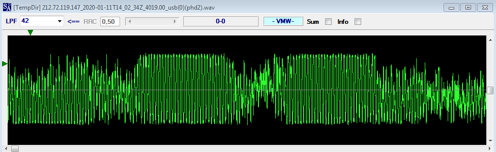
The raster shows a distortion of the manipulation speed which is also visible in the phase detector (Fig. 2): most likely a native defect of the source modem/transmitter.

Fig. 1
Fig. 2
Although quite uncommon, the baud rate is 35.5 Bd, as shown in Figure 3 where I isolated and analyzed a "clean" signal segment. It's the first time for me I meet such speed in a FSK waveform (only in CIS-60 HDR modem) but it must be said that there is a possibility that the speed will change when switching from idle to traffic mode (as the old BEE 36/50 did), unfortunately during my listening the signal remained in idle mode.

Fig. 3
As for the source of the signal, it is reasonable to think of a Russian user since the shift of 1000 Hz is used in waveforms such as CIS-14, Vezha-S and also Akula as well as used by Rus-AF (1). Nevertheless, Indian Navy too (VTH9) uses 1000 Hz shift in their FSK 50Bd transmissions.  
Although I have been keeping an eye on that frequency, to date I have not yet had the opportunity to hear this signal again.

kiwi-kuo.aprs.fi_2020-01-23T10_26_37Z_10548.50_usb.wav

(1) REA4 Moscow AF HQ  uses FSK 50Bd/1000 in idling between skeds in FSK Morse (5FGs).

22 January 2020

SkyOFDM 28-tone 86Hz 65.6Bd PSK2 (2)

Just for background it might be helpful to read the previous post.

Most likely the signal that is continuously transmitted on 4150 KHz/usb is a modded or a new waveform of the Skysweep Technologies proprietary "SkyOFDM" family. SkyOFDM is a high speed modem based on the OFDM and turbo coding technologies.  It offers several baud  rates (300-9600  bps) and two different interleaving options (short and long). Also there are two bandwidth options: 2000Hz (OFDM 22 tones) and 2400 Hz (OFDM 28 tones).

Fig. 1 - SkySweeper running the SkyOFDM modem
I tried the SkyOFDM modes available in SkySweeper 5.13 (Fig. 1), a Windows based product for radio data decoding and signal analysis developed by SkySweep.  As expected, I could not synthesize the exact waveform running on 4158 KHz since the different speeds, modulations, and ACF:

params SkyOFDM 4150 Hz OFDM
bandwidth (Hz) 2000, 2400 2400
preamble 7 tones 7 tones
tones 22, 28 28
shift (Hz) 86 86
Baud rate 60.56, 64, 79 65.57x
modulations PSK2, PSK4, QAM PSK2/SDPSKx
ACF (ms) 78, 113.4 76.2x


A peculiar difference lies in the type of the used modulations: for example, if you filter out and look at the modulation used in the second channel, you will see that is not PSK2 but SDPSK (Simmetric Differential PSK), thus it seems that channels are mixed artfully (Fig. 2 ).

Fig. 2
In SA Phase-Plane using n-Ary = 4 and absolute mode (diff=0) the transitions between states are similar to QPSK but without diagonal paths; in differential mode (diff=1) we see transitions between two states (Fig. 3) (1).

Fig. 3
According to some utility DXers, SkyOFDM waveforms were used by Finnish MFA and that's correct since SkySweep Technologies is a Finnish high tech company. Although there are still many references in the web to SkySweep, their official website is no longer online: this suggests a ceased activity or an incorporation into another company. Indeed, looking at waybackmachine.com, the site skysweep.com was crawled last time on 13 June 2017; by the way, SkySweeper software was discontinued on June 1st 2009.
That said, the permanence of this signal on 4150 KHz and its purpose are still unknown to me as well as other friends.


(1) PSK encodes the input data sequences in pahes (states), while Differential PSK (DPSK) encodes the input data in the phase difference (transitions) between successive bits or symbols. This means that there would be a phase change in the modulation signal if the two successive bits in the input data sequence are different (0 to 1 or 1 to 0), and no phase changes if the successive bits are the same. DPSK is called conventional DPSK (or CDPSK) if the phase differences is in the set of [0,π] and symmetrical DPSK (SDPSK, also called π/2-DPSK) if the phase difference is in the set of [π/2,-π/2]. As you see in Fig. 3 the transitions in differential mode (diff=1) are in the set of [π/2,-π/2] so most likely it's a SDPSK (π/2-DPSK). 

18 January 2020

unid SkyOFDM 28-tone 86Hz 65.6Bd PSK2

Continuous ofdm bursts transmission picked up on 4158 KHz/USB thanks to the "ArcticSDR" in Kongsfjord Arctic Norway: a KiwiSDR managed by my friend Bjarne Mjelde
http://arcticsdr.ddns.net:8073/ 
https://www.facebook.com/groups/1628656197277661/

Timings of the transmission and its spectrum are shown in Fig. 1 

Fig. 1 - timing and spectrum
The analysis of the OFDM signal clearly shows 28 channels and a frequency spacing of ~86 Hz, each channel is modulated using PSK2 at the symbol rate of 65.57 Bd (Fig. 2). The same results are obtained/verified by analyzing a single channel as shown in Fig. 3 (higher channel).
 
Fig. 2 - OFDM analysis
Fig. 3 - anlysis of the higher channel (#28)
As you see in Fig. 2, I did a further analysis after resampling the signal at 10109 Hz. Indeed, I used the tool OCG [1] in order to calculate and sythesize an OFDM waveform having the same parameters (channels, Br, Shift, modulation, width,...) and got 10109 Hz as one of the possible "native" sampling rate. The analysis of the synthesized OFDM is visible in fig. 4: notice the similarity between the PSK2 constellation of the synthesized signal and the one of the real signal (although resampled).

Fig. 4 - analysis of the synthesized OFdM-28 signal
The seven initial tones last 30 symbol periods and are derived from the OFDM generator as shown in Fig. 5; more precisely the used tones are: 2, 5, 6, 9, 13, 16, and 19.

Fig. 5 - initial seven unmodulated tones
The autocorrelation has a value of 76.2 ms (Fig. 6) that makes a 140 symbols length frame if considering an aggregate speed of ~1836 Bd (65.57 x 28).

Fig. 6 - autocorrelation
A similar OFDM waveform but with shorter and different bursts (Fig. 7) was reported on 2016.02.05 by my friend Cryptomaster [2] just on the same frequency of 4158 KHz/USB. In that case the modulation used was a form of PSK4, anyway number of tones, shift, Br, and ACF are the same; thus, that signal is on-air since several years.


Fig. 7
As regards the signal source, several TDoA tries always indicated an area north to Helsinki as probable Tx site (Fig. 8) although qrg.globaltuners.com reports exactly the same waveform/spectrum (and frequency too) indicating it as a signal sourced by the Spanish Navy [3].  In my opinion that's quite odd since the signal is fairly well received in the northern European countries such as Sweden, Norway, and Finland, while it is rather weak or inaudible at all in south Europe... I don't think of such a long skip.

 
Fig. 8 - TDoA reults

In my opinion it's an evolution of the original Skysweep Technologies proprietary waveform named "SkyOFDM", probably used by Finnish MFA (thanks to Roland Proesch for the hint). Indeed, the mentioned recording by my friend Cryptomaster just matches the features of the "original" SkyOFDM waveform (Fig. 9).

Fig. 9 - Skysweep Technologies OFDM-28

It's worth noting that SkySweeper Pro 5.13 software does not recognize the "new" OFDM-28 PSK2 that is analyzed  in this post.
(to be continued)

arcticsdr.ddns.net_2020-01-15T04_36_08Z_4159.70_iq.wav
synthetized_ofdm28_r10109Hz.wav

[1] OCG is a program for calculating and synthesizing OFDM signals, it can be downloaded from here
[2] http://www.radioscanner.ru/files/unknown/file19060/
[3] http://qrg.globaltuners.com/details.php?id=17420

13 January 2020

COMSEC transmissions using a S4285 variant (2)

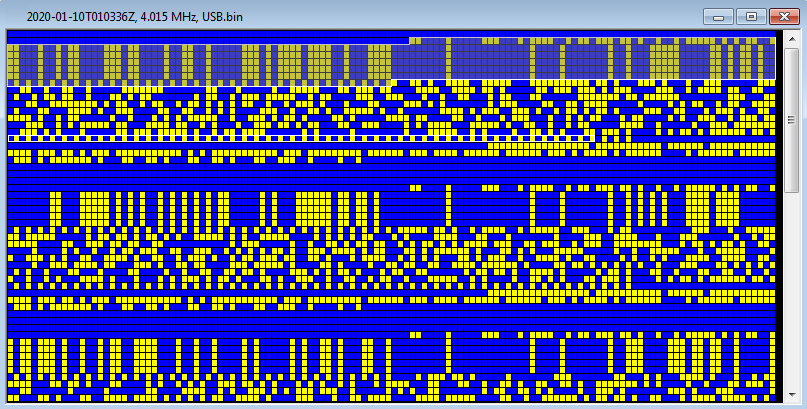
Secured burst transmission using a modified S4285 waveform [1] spotted around midnight on 4015 KHz/usb, the S4285 mode is 600bps and short interleaver. 

Fig. 1
After demodulation, the COMSEC preamble resembles 188-220D std and consists of 3 parts (my guess):
1) 60-bit Frame Sync (110000100000111000101111001011011101101001001011111010101100)
2) 5 x 128-bit strings, encoded Message Indicator (five times repeated)
3) 64-bit idling sequence (time to load the key?)

Preamble is followed by the encrypted data block which ends with "01" sequences.
 
Fig. 2 - demodulated stream of bursts

Fig. 3 - COMSEC preamble (my guess)


https://yadi.sk/d/nY-DTuTz-ZWG8g  (2020-01-10T005300Z, 4.015 MHz, USB.wav)
https://yadi.sk/d/oIHVEWbUO0_few   (2020-01-10T010336Z, 4.015 MHz, USB.bin)

[1] The same modified S4285 waveform was met here on 6931 KHz/usb:
http://i56578-swl.blogspot.com/2018/06/comsec-transmissions-using-s4285.html 

Speed distortion in an FSK signal

Most likely modem instability is the cause of the distortion in the manipulation speed (~42 bps), as it's evident in SA raster.


https://yadi.sk/d/qT-d1A_5bFtJHg

2 December 2019

Unid FSK 400 (401)Bd/800 bursts
(i56578, cryptomaster, KarapuZ)


Unid FSK 400Bd (401)/800 bursts spotted on 13224.0 Khz (cf + 1700), slight distorsion in the speed. ACF=0, no other results if demodulated using differential mode. Transmissions are not frequent and most often consist of a single burst, sometimes two (maybe two stations).

Fig. 1
Quoting my friend KarapuZ "Despite the good recording quality and SNR ratio, in my opinion, the transmitter modulator malfunctions in the frequency discriminator. As a result, we have a bitstream with many errors at the output".

Fig. 2
Comments by my friend cryptomaster follow.
The signal structure of the first burst is shown in Fig. 3, the transfer is considered without translating it into a relative form:
1. A meander with a frequency of 150 Hz (300bps);
2. The preamble is 31 bits (300bps) of the form 0101110001101000010010001010101;
3. Information transfer with a speed of 401.3 bps;
The preamble is marked in yellow:
 
Fig. 3

Other than the frequency discriminator, the signal is distorted by the imposition of a stray frequency of 800 Hz, the intensity increases by the end of the transmission (Fig. 4), perhaps this frequency (800 Hz) is somehow connected with the formation of the separation of the frequencies of manipulation.

Fig. 4
On a bitmap, it looks like the pattern in Fig. 5:

Fig. 5

https://yadi.sk/d/bJ-_r5MwVZDonQ
 

19 November 2019

Indian Navy STANAG-4285 naval broadcasts (tentative)

Follwing a tip from my friend KarapuZ and his recent tweet, I started to monitor 16941.0 KHz to study the STANAG-4285 naval broadcasts from the Indian Navy [1]. They use the quite rare 2400bps/Long sub-mode and decoding produces a lot of errors just due to the high data rate and the huge QSB that sometimes affects the signals. By the way, I used the KiwiSDRs VU Hams located in Kottarakkara Kerala and colombo4s7vk located in Colombo Sri Lanka, the latter is a bit less recommendable.

Fig. 1 - one of the S4285 2400/L heard broadcasts
For what I could see, daily broadcasts starting around 1100 or 1200 Z are transmitted on that frequency. Broadcasts consist of clear-text weather bulletins and 4FG messages to VWGZ (VWGZ is the collective callsign for any/all the Indian Navy ships): indeed, they typically use a four FIG (off-line) encryption system. Either the bulletins and 4FG messages, are sent using the async ITA2 8N1 framing (Figs. 2, 3). 

Fig. 2- 8N1 bitstream after decoding
Fig. 3 - off-line decoding using Harris RF-5710A modem
It is interesting to take a look at some bulletin/message typical contents.

VWGZ
VND 677/16
ECHO BRAVO ZULU
ALPHA KILO UNIFORM
OSCAR KILO NOVEMBER
PAPA ECHO HOTEL
ROMEO QUEBEC XRAY
INDIA INDIA HOTEL
LIMA CHARLIE PAPA
DELTA HOTEL KILO
-P- 160732
GR 158
BT
ZERO ZERO ZERO EIGHT ALFA TWO TWO FOUR EIGHT 9838
6469 5315 6155 6433 5098 8353 7507 5237 5375 4271

...
8394 6708 1257 6554 6238 5987 3600 6023 9076 1083
4574 3021 1116 0342 6063 4300 2248 0008ALFA

BT
GR 158
NNNN

AAAAFIN0M0N9O8P7Q6R5S4T3U2V1
&&&&&&&&&&&&&&&&&&&&&&&&&&&&&&&&&&&&&&&&&&&&&&&&&&
**************************************************

A1B2C3D4E5F6G7H8I9J0

where:

VWGZ 
collective callsign for any/all Indian Navy ships

VND 677/16 
indicates the daily serial number of the message in that broadcast, i.e. message #677 of day 16 (indeed 16 november, date of my reception). Don't know what VND stands for.

ECHO BRAVO ZULU 
ALPHA KILO UNIFORM
...
most likely the daily encrypted callsigns for specific ships

-P-
precedence indicator of the message
-R- Routine
-P- Priority
-O- Immediate (Operational Immediate)
-Z- Flash
  

160732
date time of origination, no time zone indicator (!)

GR 158
the number of 4FG in the message (158 in this case)

BT
separation (break), as the usual Morse Code abbreviation 

The 4FG block is always preceeded by a 9 chars string, i.e.: 

ONE NINE NINE TWO ALFA NINE SEVEN TWO FOUR 

I noted that this string is used to "signal" the last two 4FG in the block, respectively the last and the second-to-last:
 
ONE NINE NINE TWO ALFA NINE SEVEN TWO FOUR 9072
2299 4827 3953 0701 6748 2577 4084 8109 5655 4999
...
5904 4854 4358 8628 9964 9687 9032 0282 4140 7567
5029 5582 1302 9724 1992ALFA
;
ZERO ZERO ZERO EIGHT ALFA TWO TWO FOUR EIGHT 9838
6469 5315 6155 6433 5098 8353 7507 5237 5375 4271
...
8394 6708 1257 6554 6238 5987 3600 6023 9076 1083
4574 3021 1116 0342 6063 4300 2248 0008ALFA
;
ZERO THREE NINE NINE ALFA ZERO SIX FIVE NINE 7346
0822 9678 3021 3357 0524 0160 9645 0013 4927 1959
...
5457 3192 3301 5013 5856 9799 0272 2857 8727 9046
1854 5256 7000 0659 0399ALFA


The 4FG blocks usually end with the separation char (BT) folowed by the repetition of the number of encrypted groups in the message (GR nnn), the usual RTTY end-of-message (NNNN) and the strings: 

AAAAFIN0M0N9O8P7Q6R5S4T3U2V1
&&&&&&&&&&&&&&&&&&&&&&&&&&&&&&&&&&&&&&&&&&&&&&&&&&
**************************************************

A1B2C3D4E5F6G7H8I9J0

at present I do not know their scope/meaning, maybe test chars, but it makes some sense if they are read respectively as couples [0;1][M;V]:

AAAA
FIN (=finish ?)
0M
0N
9O
8P
7Q
6R
5S
4T
3U
2V
1


and [A;J][1;0]:

A1
B2
C3
D4
E5
F6
G7
H8
I9
J0 


It's worth noting that  in each transmission the most recent message is sent as first (a kind of LIFO). Moreover, some of the messages that were sent in the previous broadcast are re-inserted in the current one, i.e. the broadcast of 1304 Z contains the last message (#679) and the twos (#678 and #677) sent in the previous broadcast of 1255 Z
 

[2019-11-16 1152Z]
VND 677/16
VND 676/16
VND 675/16
VND 674/16

[2019-11-16 1255Z]
VND 678/16
VND 677/16
VND 676/16

[2019-11-16 1304Z]
VND 679/16
VND 678/16
VND 677/16


Probably this method is used to improve the reliability of the system but it is not clear to me how the number of messages to be repeated is determined (precedence? duration?).
Sometimes it's possible to see short messages as:

VWGZ
VND 675/16
ZFA
VTH DE GOLF YANKEE
-O-
LIMA ROMEO MIKE
FOXTROT KILO NOVEMBER
160801
ZBQ 0805
BT
NNNN


VTH is listed as the callsign of Indian Navy Mumbai.
Note the Z codes ZFA (Following message has been received) and ZBQ (Message was received at).


Weather bulletins report Weather, Surface Wind, Visibility, Sea State, Swell, and Warnings for specific areas and period of validity (12 hours). The bulletins header indicates the originator of the message just after the precedence indicator: 

-P-  150320
FROM FOCINC EAST
TO   ALL CONCERNED

-R-  141004Z
FROM NAVAREA VIII CO-ORDINATOR
TO   NAVAREA VIII

-P-  160900
FROM CINCAN
TO   ALL CONCERNED


where:

FOCINC EAST: Flag Officer Commanding-in-Chief Eastern Naval Command. The Indian Navy operates three operational Commands, each headed by a Flag Officer Commanding-in-Chief (FOCINC): FOCINC East (Visakhapatnam HQ), FOCINC West (Mumbai HQ), FOCINC South (Kochi HQ).

NAVAREA VIII CO-ORDINATOR: the Chief Hydrographer to the Government of India.

CINCAN: Commander-in-Chief of the Andaman & Nicobar Command. The Andaman and Nicobar Command is the first and only Tri-service (army, navy, air force) theater command of the Indian Armed Forces.

Since some of the weather bulletins also report detailed "LOCAL WEATHER FORECAST FOR VISAKHAPATNAM", probably the broadcasts are transmitted from a COMCEN belonging to the Eastern Naval Command (ENC) HQ in Visakhapatnam [2]. In this respect it's noted that some logs in old WUN/UTNL newletters report "VTP Visakhapatnam" as Indian Navy station operating in CW and RTTY 50Bd/850, but not on 16941 KHz. Actually, I didn't find any "official" allocation for 16941.0 KHz but only a clue related to one of the frequecies that are used for HF communications in the Indian activities in Antarctica (IAP, Indian Antarctic Programme) [3].
Given the period of validity (12 hours, except for the forecast for Visakhapatnam which have 24 hours validity) it makes sense to expect similar broadcasts around 0000Z, likely on a lower HF band.
(to be continued)
kiwisdr.vuhams.net_2019-11-16T12_55_40Z_16941.00_usb.wav 

[1] https://en.wikipedia.org/wiki/Indian_Navy
[2] https://www.indiannavy.nic.in/node/1399#
[3] inpre07e.doc 

4 November 2019

Baudot FSK 100Bd/500 (unid Rus Gov/Mil)

Interesting async ITA2 5N1.5 FSK 100Bd/500 tuned on 11019.0 Khz some days ago. Once demodulated, the content consists of (off-line) encrypted 5LGs groups. Note also the slight deviation of the speed.


The transmission ends with the FSK-MORSE op-chat "CFM QRQ 100 QBN K": almost surely Russian Gov/Mil users.


Same 5LGs format and 5N1.5 framing was found in the reception reported in this post, with the difference that the latter has a speed of 50 Baud.


17 October 2019

async FLSU call followed by STANAG-4197 (3G-HF "circuit mode")

This transmission was logged and recorded by my friend DK8OK Nils on 11228.0 KHz/USB, and refers to op-comms between  "INY" Trapani-Birgi airport and "DHN66" Neuteveren/Geilenkirchen NATO air base (INY provides technical-operational and logistical support to the AWACS of the E-3A Component, based in Geilenkirchen). Nils kindly sent me the file for its analysis.
The sample is an example of a STANAG-4538 3G-HF FLSU (Fast Link Setup) asynchronous call followed by traffic in "circuit mode" (data continuous, not packed); short voice comm is in the middle. Although synchronous calls are the preferred mode in 3G networks, async calls might be used if the called (or the caller) station may not have achieved net synchronisation. 
The BW5 burst waveform used by FLSU is recognizable in the initial PSK-8 segment from its duration and from the conveyed tribit symbols (2432), as it results from the cross correlation function and the demodulated stream (Fig. 1).

Fig. 1 - CCF/ACF and demodulated stream
According to Annex C to STANAG-4538, the async call of FLSU protocol begins with the LBT (listen before transmit) for at least one dwell period, followed by the transmission of 1.35N (nearest integer value) Async Request PDUs on the requested link frequency, where N is the number of channels in the scan list, and 1.35 is the duration of each dwell period in seconds. The async call procedure ends with a single LFSU Request PDU (Fig. 2).

Fig. 2 - async FLSU PDUs
Looking at the 50-bit payloads in Fig. 2, type 3 (011) PDUs are sent 10 times and are followed by a single type 0 (000) PDU: since PDUs type 3 indicate the Async_FLSU_Req PDU, and type 0 indicates the FLSU_Request PDU, the sample exactly matches the async call procedure as above. By the way, it's worth noting that since up to 10 Async_FLSU_Request PDUs are used, 7 are the allocated channels for this network.


001 00 0000101000 0000001010 1 0 011 111111 010010 11011011
001 00 0000101000 0000001010 1 0 011 111111 010010 11011011
001 00 0000101000 0000001010 1 0 011 111111 010010 11011011
001 00 0000101000 0000001010 1 0 011 111111 010010 11011011
001 00 0000101000 0000001010 1 0 011 111111 010010 11011011
001 00 0000101000 0000001010 1 0 011 111111 010010 11011011
001 00 0000101000 0000001010 1 0 011 111111 010010 11011011
001 00 0000101000 0000001010 1 0 011 111111 010010 11011011
001 00 0000101000 0000001010 1 0 011 111111 010010 11011011
001 00 0000101000 0000001010 1 0 011 111111 010010 11011011
001 00 0000101000 0000001010 1 0 000 111111 010010 01001101

The STANAG-4197 waveform following the call is most likely used in a ANDVT modem in order to achieve secured voice transmission.  
Notice the apparent lack of the fourth doppler tone at 2812.5 KHz: indeed, it's seems just barely visible in the bottom sonagram of Fig.3: probably a defect/malfunction of the HF modem. 

Fig. 3 - STANAG-4197 segment