27 February 2021

15-channel BPSK 500Bd 30KHz, CIS (wideband?) Akula

Quite rare Akula ("Shark") [1] signal catched by my friend KarapuZ. The usual Akula 500Bd/1000 FSK2 waveform is preceeded by the transmission of 15 PSK tones (MPSK-15) lasting the same time of the FSK signal. The 15 channels are about 2200 Hz spaced and occupy a bandwidth of 30 KHz, each channel consisting of a BPSK modulated tone at the symbol rate of 500Bd (Akula II), ie the same of the following FSK2 burst; the 15 subcarriers are not orthogonal (Figs 1,2).

Fig. 1

Fig. 2
 
Either the BPSK channels and the FSK2 transport the same data and use the well-known distinctive sign "1771/"  as shown in Figure 3.
As per [1], FSK2 Akula may be descrambled using the LFSRs described by the polinomyals x^5+x^3+x+1 or x^4+x^3+1 after differential decoding: well, in this case none of the two modes (BPSK and FSK2) is successfully descrambled using the above polynomials.
 
Fig. 3 - ending parts of the demodulated bitstreams

The FSK2 signal is exactly centered on the passband of the preceeding 8th DBPSK tone (likely the "call" frequency): it could be that the FSK2 signal is targeted to "legacy" receivers while the wideband part to "stared" SDR receivers (as said, the contents are the same)... but that's only a my guess, who knows? anyway, using such a width signal (about 30 kHz) should provide good noise immunity. It's to notice how the power of the FSK signal appears spreaded on the DBPSK signals (same transmitter). 
 
The use of BPSK modulation (Akula II) is not new, as a 2015 recording demonstrates (Figure 4). Also in this sample, the FSK signal is centered on the passband of the preceeding BPSK subcarrier, although the switch time  BPSK -> FSK2 is longer than the one 15xBPSK -> FSK2. The two demodulated bitstreams - at least in this sample - are not the same (Figure 5).
 
Fig. 4 

 
Fig. 5


23 February 2021

a STANAG-5066 (off-line) dissector


S5066 dissector (free software licensed under the GNU General Public License - GPL) is a GNU Octave coded tool that accepts as input a filename.txt file containing a stream of ASCII 0's and 1's (no space between) and, accordingly the input arguments, prints out:
a. filename_out file containing the decoded headers of the STANAG-5066 stack (DTS, CAS, SIS)
b. filename_addr file containing the changes of the traffic flow direction  (change of the source and destination node address)
c. filename_<n> files containing the user-data in ASCII-bits or ASCII-chars format
The output of the decoded headers is also shown on the Octave Command Window (the Command Window anyway does not allow you to browse the whole output).
The STANAG-5066 stack is scanned bottom up (starting from DTS layer)  as if the bistream were being parsed by a receiving node; since the dissector goes back up to the user data, it also shows some informations about the User-to-User Protocol as well as the Client Application type (BFTP, TTHMS, FRAP,...) and the basic transport protocol (RCOP/UDOP).
The input ASCII file being analyzed may be produced by a modem or a decoder (such as sorcerer, k500,...) which have the task of removing the HF waveform overhead (110A, S-4285, S_4539, ...), therefore this dissector is an "off-line" tool: a real-time version needs much more work (and code) other than a pc with the synchronous interface (users' standard pc are equipped with async interfaces).
The dissector is primarily thinked to work on (decoded) on-air symbols, hence its goodness will depend either on the quality of the signal and the precision of the modem/decoder. This is a beta and anyway STANAG-5066 Edition 3 compliant version: bug-fix (and maybe Edition 4 compliant) releases will follow.

Requirements:
1) GNU Octave >= 6.1 (see this post for Octave installation)
2) the input file should contain only '0's and '1's, ie no spaces or some other separator char between the values; preferably without LF/CR: in that case the software will reshape the contents and warn the user with the message "reshaping file, wait..."

Usage:
S5066(fn,i,f,cout,t)
  fn = filename containing a stream of ASCII 0's and 1's
 i,f = range of frames to be processed (i=0 first, f=0 last)
       0,n [1 - n]
       n,0 [n - last]
       n,m [n - m]
       n,n [only n-th frame]
cout = 0 do not extract user data (do not reassembly C_PDUs)
     = 1 extracts the user data in ASCII-bits format (0's and 1's)
     = 2 extracts the user data in ASCII-char format
   t = 1 tracks the changes of the flow direction (0 = no action)

Usage examples (notice that at each run the previous output files are overwritten):
S5066 ("test.txt",0,0,0,0)
process all the frames of the file and prints out the file:
- test_out.txt

S5066 ("test.txt",0,0,2,1)
process all the frames of the file and prints out the files
-  test_out.txt
-  test_addr.txt
- test_<n>.txt files containing the user data (as many files as the reassembled C_PDUs); since the parameter cout has the value 2, the user data files are in ASCII-char format (Extended ASCII code is used, a proper editor is recommended) 

A short report is printed at the end of the headers file along with the "elapsed time"; by the way, the time taken depends on several elements:
- the need to reshape the input file
- if user data extraction is required and its format (bit/char)
- the number of frames to be processed (length of the input file)
- type of data transfer
and - obviously - on the performances of your pc. Below an example of two reports the same input file (s23.txt, 1Mb length) with and w/out reshaping:


Installation
Download S-5066.ZIP and expand it in your Octave directory, usually c/users/<your_name>/octave. Will be created the S-5066 directory containing the files "README.txt" and "test.txt" along with the subdirectory /m which contains the Octave scripts.


Change the working directory to .../octave/S-5066 and run the command addpath ("./m") so that Octave will know where to look for .m files: as usual, the /m subdirectory 

then you can run and try S5066 using the input arguments that you prefer. The test.txt file contains a STANAG-5066 bitstream relating to a real on-air transmission: ie it does not have  a "perfect" protocol layout as if it were captured at the output of a STANAG-5066 server. I also want to remember that S5066 is a passive dissector only and does not simulate a receive node (it does not implement timings, receive windows, and other stuff).
Below some commented examples of output files (headers files): their study may offer some useful insigths to understand how STANAG-5066 works. 

Figure 1 is related to the simple ARQ service (type 0 D_PDU), the frames from 141 to 152 allow to follow the transfer of a segmented C_PDU.

 
Figure 1

A) The C_PDU START flag of the frame #142 is set to indicate the start of a newly segmented C_PDU; the C_PDU segment contained within this D_PDU is the first segment of the C_PDU; the C_PDU END flag is clear. In frame #152 the C_PDU START is clear and the C_PDU END flag is set to indicate the end of a segmented C_PDU.
 

B) The first segment is conveyed by the D_PDU with sequence number #22, the last segment by the D_PDU with sequence number #32, ie eleven D_PDUs. As expected from the encapsulation (each sublayer adds its header), only the D_PDU with the initial C_PDU segment (sequence number #22) is followed by the other sublayer headers (CAS, SIS, and user protocol) while the following D_PDUs contain only a C_PDU segment.

C) The EOT (End Of Transmission) field provides an approximation of the time remaining in the current transmission interval from the beginning of the current D_PDU. More precisely, the number in this field is a binary number expressing the number of half (1/2) second intervals, thus the flow controll allows a maximum transmission interval of about 2 minutes.
 

D) As you can see in the size of segmented C_PDU field, each segment has a size of 200 bytes, except the last segment which is 26 bytes length. The whole C_PDU is then composed of (200x10)+46 = 2046 bytes; adding the headers of the (11) D_PDUS needed to convey the segments we get a total of 2246 Bytes. Since that the needed transmission time is about 15 seconds (difference of the EOT fields), the transfer speed is 1200 bps.

If all D_PDUs between and including the C_PDU START and C_PDU END (frames from 142 to 152) are received completely error free the link layer will assemble the C_PDU segments and deliver the result to the higher sublayers.
 
C_PDU Re-assembly for ARQ Delivery Services
 
Figure 2 is related to the NON-ARQ service (type 7 D_PDU), the frames 1-6 allow to follow the transfer of a segmented C_PDU.
 
Figure 2
 
A) Instead of the start/end flags mechanism seen in ARQ service, the NON-ARQ service signals the start and the end of a segmented C_PDU by means of the C_PDU segment offset field and the (unsegmented) C_PDU size field; the D_PDU with the C_PDU segment offset = 0 indicates the first segment (ie the the start of a newly segmented C_PDU). The end of a segmented C_PDU is reached when the sum of the received segments sizes is equal to the C_PDU size field (ie 1078 in this example). Notice also that all D_PDUs containing segments from the same C_PDU have the same C_PDU ID number (in this case 2570).

B) The EOT field has obviously the same meaning seen in the ARQ service example (time remaining in the current transmission interval).

Each segment has a length of 200 bytes, except the last which is 78 bytes length. The whole C_PDU consists of 1078 bytes; adding the headers of the (6) D_PDUS needed to convey the segments we get a total of 1222 Bytes. Since that the needed transmission time is about 6 seconds (difference of the EOT fields), the transfer speed is 1600 bps.
The re-assembly process for Non-ARQ C_PDUs uses the C_PDU ID Number, Segment-Offset field, C_PDU-Segment-Size field, and C_PDU-Size field to determine when all segments of a C_PDU have been received.The segments that are reassembled are expected to have passed the CRC error-check and have no detectable errors.
 
C_PDU Re-assembly for NON-ARQ Delivery Services

Figure 3 is related to the tracking of the traffic flow direction, still in experimental version. That feature coud be useful in case of a recording of a ARQ-type session which comprises both data and ACKs sendings. At present, it simply records the changes of the SENDER/DESTINATION address along with the D_PDU type and frame number. 
 
Figure 3

Although the dissector does not care the user data, it also provides a raw(!) extraction and reassembly of the C_PDU segments.
 
 
Some features as the tracking of the traffic flow direction, controls/checks of inconsistencies and some other ones as the CRC check and C_PDUS segments reassembly, will be implemented in next releases.
Comments, suggestions and bugs reports are welcome!

17 February 2021

Fast WALE Async call (4G-ALE)

In the asynchronous call, used to set up a link between two stations when one or both of them is scanning asynchronously, the WALE Request PDU must be preceded by a scanning call, the "capture probe", which similarly to 2G/3G ALE is aimed to capture asynchronously scanning receiver(s).

Asynchronous two-way point-to-point link setup example (from MIL 188-141D App. G)

The capture probe consists of repeated blocks of known symbols that will be recognized by the scanning receivers so that they will stop scanning and wait to receive the WALE Request PDU (Protocol Data Unit) which immediately follows the capture probe section. The capture probe must last long enough so that every scanning receiver will have a chance to receive it, thus its duration depends on the number of channels (N) in the scan set and on the minimum dwell time Dmin (200 ms as default setting) and shall be  ≥  Dmin * (N+2).

In the sample being analyzed the "Fast" WALE waveform [1] is used to convey the WALE Request PDU which follows the capture probe (figure 1).

Fig. 1
 
Each capture probe block consists of the following 96 PSK8 symbol sequence:
 
1,1,4,6,5,5,5,2,4,7,6,7,7,3,3,0,5,5,7,4,2,7,2,5,2,7,2,6,6,6,0,4,
6,1,0,7,1,2,1,6,3,2,0,2,5,5,2,7,3,1,0,4,7,7,7,7,2,6,5,6,6,7,0,2,
0,1,2,5,6,1,7,7,4,0,4,7,4,5,4,4,1,4,2,2,2,4,6,7,3,4,5,5,1,0,3,0
 
and, since it's transmissed at the symbols rate of 2400 symbols/s, each block has a duration of 40 ms. Notice that the number of the known symbols in each block (96) is the same of the number of the unknown symbols sent in the call PDU: most likely this choice was adopted to facilitate the recognition and acquisition of the ending call. 
Figure 2 shows the 40 ms ACF spikes of the scanning call portion.

Fig. 2 - ACF of the capture block section

It's interesting to compare the way 3G-ALE (STANAG-4538) and 4G-ALE (MIL 188-141D WALE) implement the async calls: 

• the 3G-ALE async call consists of 1.35 N  "011-type" Request PDUs, where N is the number of  frequencies in the scan list, and 1.35 is the duration of the dwell period (in seconds); the call ends with a single "000-type" PDU Request. Since the address of the called station is contained in each of the "011-type" PDU Requests (as in 2G style), all stations that are not included in the call are free to resume scanning;
• since the 4G-ALE async call is not addressed, a station must wait for the Request PDU (sent at the end of the capture probe) to find out if it is the recipient of the call. 
 
It might seem like a disadvantage, but 4G is actually much more faster that 3G; indeed, assuming a 10 channels scan set, the maximum wait duration is approximately equal to 13.5s for 3G and 2.4s for 4G (with minimum dwell time of 200 ms).
 

13 February 2021

install, run and test GNU Octave against T207 and CIS-11 streams

updated

This is just a quick how-to for Octave since some friends asked me for some tips about the installation and use of Octave with some analysis tools such as the ones for T207 and CIS-11 streams (...and hopely soon for the STANAG-5066 dissector).
GNU Octave is a high-level interpreted language, primarily intended for numerical computations. It provides capabilities for the numerical solution of linear and nonlinear problems, and for performing other numerical experiments. It also provides extensive graphics capabilities for data visualization and manipulation.
The GNU Octave language is largely compatible to Matlab so that most programs are easily portable. In addition, functions known from the C standard library and from UNIX system calls and functions are supported. C/C++ and Fortran code can be called from Octave.

The easiest way to install GNU Octave on Microsoft Windows is by using MXE builds. For the current release, both 32-bit and 64-bit installers and zip archived packages (.zip and .7z formats) can be found here under the Windows tab:
https://www.gnu.org/software/octave/download.html 
For executable (.exe) installers (the better way) the user can simply run the downloaded file and follow the on-screen installation prompts. It is recommended that the installation path does not include spaces or non-ASCII characters. Shortcuts to the program will be created automatically on the desktop: CLI for the command line and GUI for the graphic user interface, the latter (GUI) is the one that is normally used:

 The installation steps are shown below:


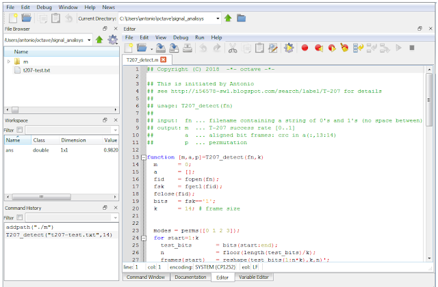
After the installation is finished you will have to create the main working directory, usually c/users/<your_name>/octave; this will be the the right place where to create the sub-directories to store the Octave .m scripts. For example, create the sub-directory /signal_analysis and download the file t207-test.txt to it, then create the sub-directory /m (within /octave/signal_analysis) and download the script T207_detect.m into the /m sub-directory (T207_detect.m is a tool to verify the presence of the so-called T207 "format"). Now double click on the GNU Octave GUI icon and Octave will start in its Command Window


Change the Current Directory from  /octave to /octave/signal_analysis by using the arrows of the file browser, and then run the two commands:

addpath ("./m")
T207_detect ("t207-test.txt",32,14)

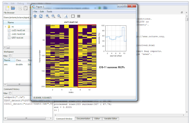
The first command (addpath) tells Octave where to look for the invoked .m scripts, i.e. the su-b-directory /m where you previously downloaded the script T207_detect. The second command launches the T207_detect.m script which will process the file t207-test.txt: an ASCII-bit file containing a demodulated FSK bitstream, i.e. the file to analyze that you previously downloaded to the /signal_analysis sub-directory (the other parameter is the desired frame size, 14).


after few seconds (depending on the speed of your pc) you will see the result of the T207 detection:


After close the Figure 1 window, you may also see the results shown in the textual form. Now Octave is ready to accept a new command:

You can switch to the Editor Window in order to open and edit the scripts in the /m sub-directory


Well, in the same way as above, now you can analyse - for example - a bitstream to check the presence of the CIS-11 format:

1) download the .m script CIS11_detect.m to the sub-directory /octave/signal_analysis/m
2) downolad the files cis11-test1.txt  and  cis11-test2.txt to the sub-directory /octave/signal_analysis
3) switch to the Command Window and run the command  CIS11_detect against the two files:


In a few words:
/octave/signals_analysis     > will contain the files to be analyzed
/octave/signals_analysis/m > will contain the various Octave scripts

Well, now you are probably wondering what you have done.

1) An interpreted language (as for example BASIC or Java) is a kind of programming language whose implementations execute instructions directly and freely, without previously compiling a program into machine-language instructions: the "interpreter" will convert the the high-level language code into the code understand by the operating system (say assembly language or machine-language). 

2) Well, as said at the beginning of the post, Octave is something like a "software environment" which consists of a high-level interpreted language, the interpreter, several software "libraries" that you may link to your Octave code, editor and various utilities all grouped inside the graphic user inteface. Thus when you click the GUI interface you do nothing but load and run the Octave environment.

3) When you wrote the "T207_detect" command in the Command Window, you simply told the interpreter to read and execute the Octave code language instructions saved in the "T207_detect.m" file, passing it some parameters such as the name of the data file to be examined (t207-test.txt).

4) Strictly, T207_detect.m is not indicated as a "program file" but rather as a "script file", ie a file containing any sequence of Octave commands (say instructions). It is read and evaluated just as if you had typed each command at the Octave Command Window prompt, and provides a convenient way to perform a sequence of instructions (you can't do that with a compiled language such as C). 

5) At the end of the day, T207_detect.m is nothing else that a sequence of Octave instructions that implement the algorithm described here in order to check if all the 14-bit sequences of a file verify the T207 checksum: even on large files the computer will take a few seconds, it would take hours, beer and coffee (lots of coffee ) if you do it by hand. 

Yes I know, that's a very basic approach to Octave but I hope it will allow you to start to work with some useful scripts, understand how it works... and maybe start to learn Octave. By the way, two important resources:
https://wiki.octave.org/Octave_for_Microsoft_Windows
https://it.wikipedia.org/wiki/GNU_Octave

11 February 2021

weird, but intriguing, 75bps Baudot encoding with 3.8 stop bits (prob. ACP-127 msg)

That's a very interesting Baudot 75Bd/850 FSK signal recorded (and sent me) by my friend cryptomaster on 6721 KHz/USB: although its nominal parameters lead to an async STANAG-4481 transmission, the analysis (Figure 1) reveals an unexpected stop-bit length of 3.8 bits(!), i.e. an unusual 5N3.8 framing (it's to notice that, in case of lost sync, the stop-bit stretching allows faster resync and framing of the incoming data).

Fig. 1

Since the bit editor works using integer numbers (it can't draw half bit), the bitstream is shown with the 5N4 framing  (Figure 2, negative polarity): it means that parsing the 5-bit code will inevitably produce some errors.

Fig. 2 - the bitstream as it appears after demodulation

At first glance, the decoded text looks like a message with errors due to a noisy signal or having a poor SRN (Figure 3), but an in-depth analysis of one of the decoded text reveals interesting details that allow us to identify sender/recipient and the very nature of the message: in my opinion, a radar detection report sent in ACP-127 style message. Obviously, decoding suffers from the non standard framing so, after various decoding runs, I re-built the message using the parts taken here and there and that -in my opinion - make more sense.

Fig. 3 - Baudot decoded text

T-O  081506z Fet 21
that's the DATE-TIME-GROUP (DTG)  of the message; indeed, as you can see in Figure 1, the transmission was recorded on 2021-02-08t15_12_04z so we have 08 (day 8) 0815z (time) february 2021 (Fet 21). This way of coding the date also corresponds to what is indicated in the Code FM-13-x-SHIP (or shortly FM-13) [1].

FM TIRPA 29 TO CEFAE
FM
is the originator's sign, the originator of this message is indicated by the designation immediately following. TIRPA  is the callsign adopted by the French Aviation Defense Service (ICAO DEF), TIRPA 29 could be an aircraft  [2]. TO is the "Action Addressee", ie the addressee(s) immediately following (CEFAE) is to take action on the message.

INFO AERO LANN BIHOUE
INFO is the Information addressee sign (as "CC"), in this message is the French Naval Aeronautical Base of Lann-Bihoué located in the Atlantic region, placed under the operational command of the Atlantic zone (AERONAV/AWLANT, see below) [3].

MCA ACT/AERONAV/AWLANT
likely the Aéronautique Navale (AERONAV) operational command of the Atlantic zone (Air Wing Atlantic, AWLANT). Since the "scene", MCA could mean Maritime Cryptologic Architecture (here the term "cryptology" refers to the SIGINT functions of the maritime Services and incorporates Information Security or INFOSEC functions).

NMR/004 NP 0802 TXT LR 3/1
number of the message (NMR 04), date February 8th (NP 0802) and format of the message (TXT)

DDGH/FRA/JEWNDE VIENNE
the term "VIENNE" could be misleading (city of Wien) but actually JEWNDE VIENNE stands for "JEANNE DE VIENNE", a F70 type anti-submarine frigate of the French Navy. DDGH is the acronym of Destroyer, Helo Capable, Guided Missile.

GPOSIHION 4642.7N/0023.9W SUFFIX GOWF PAPA
it's likely a (geo) position  (suffix is probably GP, GOLF PAPA ). Don't know the format the coordinates are expressed, it seems they do not exactly follow the FM-13 [1] specs even if the terms North and West are easily recognizable. Trying a parsing, the result is quite realistic (46°25'12", 2°23'24")

ROUTE/VITESSE 293 VRAA
respectively course and speed (see below)

And here things get more interesting:

RMQ:CFTERCEPTION ESM DRBV 26A X SN 40270 / CONFIANCE 3
DRBV 15 / SN 65+53 / CONFIANCE 3
 

I guess this text refers to INTERCEPTION ESM, where ESM stands for Electronic Support Measures: i.e. something related to radars [4], indeed:

- DRBV-26A (Jupiter) is a Thomson-CSF early warning radar performing long-range air surveillance on board medium and heavy-tonnage ships. DRBV-26A operates in D-Band, and is available with a cost-effective fully solid-state transmitter [5][6]
- DRBV 15 (Sea Tiger) is operating in S-Band air and surface surveillance and target designation radar. The system is designed for medium to large ships and can be integrated with weapons systems [7] [8]
- CONFIANCE is the degree of the detection confidence, levels range is from 1 (low) to 3 (high).

 SN 40270 and SN 65+53 are probably some of the out measurements from the radars.

BT /0 NNNN
Break and End-of-Message Indicator (EOM)

Since the French Navy frigate "Jean de Vienne" is equipped with both the radars (DRBV-26A and DRBV 15) [9], I think that the recorded transmission could be an ACP-127 tactical message about a radar detection (or something very similar to it). It's not clear to me who the fields position-course/speed refer to (sender? ship? or maybe the radar target?).
Anyway, it's quite unusual to see such (prob.) ACP-127 messages in clear text as well as the 5N3.8 framing, probably derived from a STANAG-4481F modem: could they be trainings? Comments are welcome.

 
Frigate Jean De Vienne (CC BY-SA 3.0, https://commons.wikimedia.org/)

Update (thanks to Jean-Marc Liotier @liotier)
CEFAE Centre d'entraînement et de formation de l'aéronautique navale, navy school in Lann-Bihoué.
Looks like training is the reason for using this elderly format to report ESM sightings.