29 December 2018

9MR - Malaysian Navy, uncommon FSK shift and ITA2 framing

(a joint analysis by me, ANgazu, Cryptomatser)


9MR 9/10/13 RMMJ MRB MRB RYRYRYRY 9MR 9/10/13 RMMJ MRB MRB SGSGSGSGSG AR JULL JULL
is the Id & "RY/SG" test tape transmitted by 9MR Royal Malaysian Navy (RMN) [1], picked up using the  VR3BG KiwiSDR located in Hong Kong and tuned on 8461.1 KHz and 6483.1 (CF).
The signals exhibit two curious features, at least in the heard test trasmissions: the first consists of the used 50Bd async FSK waveform with the non-standard and quite uncommon 900Hz shift value (Fig. 1).

Fig. 1 - 900Hz shift
The second feature is the framing which is used during the test operations: as you may see in Figs. 2 and 3, they use ITA2 code (5x28) with alternating framings 5N1/5N2, i.e., a character sent with 1 stop bit followed by a character sent with 2 stop bits (say 5N1V, a variable number of stop bits but at least one)


The variable framing causes the 15-bit period visible either in the raster of SA either in the bitstream (the latter reshaped to 30-bit in Figure 2). When a block ends, it possibly uses a special character or new line that causes te one bit shift to the left.

Fig. 2
Fig. 3
According to my friend Cryptomaster, we face a 5N1.5 framing and the synchronous equipment compensates for this disadvantage, resulting in alternation of stops with a length of 2 and 1 bit. About the unusual frequency manipulator, this is a drawback of the frequency manipulation shaper: when changing its polarity, the unfiltered classical transient process is visible (Fig. 4)
Fig.4
It could be a good reason, anyway after removing/cutting the upper and lower extra-frequencies, the signal still exhibits a 900Hz wide spectrum (Fig. 5)


Fig. 5

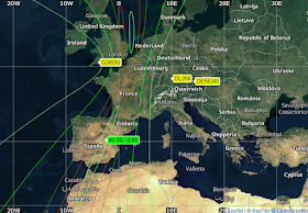
By the way, our TDoA direction findings (6483.1 KHz signal) point to Tanjung Gelang, site of RMN's Fleet HQ of the Naval Region I.

Fig.5
As a final note, the analysis of the 6483.1 FSK  transmission suggests that there maybe some flaw somewhere.
 
Fig.6


https://yadi.sk/d/d15nXWys6iSuIg (6483.1 KHz)
https://yadi.sk/d/2gmoADztQTwT0w (8461.1 KHz)

22 December 2018

some recent (unid) catches in the 8 MHz band

STANAG-4285 async operations


Transmission heard on 8167.0 KHz/usb consisting of S4285 600bps/L transfer. After demodulation, the bitstream reveals ITA2 5N1.5 async operation with encrypted data and looks like the format seen here which is possibly used by Turkish-Mil.


https://yadi.sk/d/PPd1Rl9FZHtTbQ

MIL 188-110A bursts


Since several days I've been listening to 188-110A Serial Tone bursts on 8058.0 KHz/usb, 600bps short interleaving is the used mode. Burst last 1200ms and have a spacing of 500ms.  The long (hours) sessions continuously send the same 240-bit pattern. 


Fig. 1 - 240 bit pattern (reshaped to bytes)
TDoA runs point to Spain. 

Fig. 2

 https://yadi.sk/d/tYRSkswo6gwYiA

MFSK-4 100Bd/400

short transmission heard on 8180.0 KHz/usb, unfortunatelly I went very late on it and I have not had the chance to listen to it anymore. My friend KarapuZ suggests Russian source.


https://yadi.sk/d/JnZGPnoAsoXarQ

15 December 2018

STANAG-5030/MIL-188-140 VLF/LF multichannel broadcast to submarines (tentative)

The Navy ashore VLF/LF transmitter facilities transmit submarine command and control broadcast which is the backbone of the submarine broadcast system. The VLF/LF radio broadcast provides robustness, availability, global coverage, and has seawater penetrating properties. The 200Hz assigned bandwidth for VLF/LF broadcast and the low efficiency (and narrow bandwidth) of the aerials are limiting factors, but the use of Minimum Shift Keying (MSK), a form of Quadrature Phase shift Keying, can allow optimum use of this narrow bandwidth [1]. 
VLF/LF broadcasts to submarines are STANAG-5030 compliant but unfortunately it's a restricted document so no information is publicy available. Moreover, the new STANAG-4724 is currently being ratified by NATO member states as next evolution.  However, googling the web it's possible to retrieve (few) manufacturers brochures of VLF/LF modulators/demodulators, as the one shown in Fig. 1, and get some informations. These equipments can provide TDM multi-channel broadcast (up to four channels, all 50 baud) and mainly use modulation techiniques as MSK (MSK2 2x50 Baud channels and MSK4 4x50 Baud channels), OQPSK and OOK "on-off keying" (the latter usually associated with the Morse Code).


Fig. 1
waveforms
Reference MSK modulation indicates zero-crossing transitions (eg +1/+1 to -1/-1 and viceversa, +1/-1 to -1/+1 and viceversa) cannot be allowed if phase discontinuity is to be preserved.

I analyzed some easily receivable VLF stations (DHO38, FTA, FUE, GQD, ICV, JXN, NSY, SXA, ...) and found that the phase-plane of some signals exhibits the expected transitions while others signals show odd transitions. The answer is to be found in the harmonics spectrum of the signals (Fig. 2): when the carrier is missing  the PLL algorithm locks onto one of the two spectral lines and causes the odd transitions shown in the phase-plane. The presence/absence of the carrier also makes me think of different solutions adopted by manufacturers since MSK should be coherently detected like OQPSK (that implies acquiring the carrier!) or non-coherently detected like FSK. 

Fig. 2 - carrier is missing in signals like FUE
My friend ANgazu pointed out the use of different filtering (Fig. 3). If a Gaussian filter with a Bt of 0.8 or less is in use, as in FUE, the side lobes are attenuated and the modulation is GMSK. NSY has many side lobes so, most probably, no Gaussian filter is in use and modulation is pure MSK. A special case is JXN that uses a cosine filter.

Fig. 3 - differing filterings
That being said, some equalization/correction is needed to emerge the carrier in the midlle of the two tones as shown in Figure 4:

Fig. 4 - FUE constellation after and before equalization
However (G)MSK doesn't seem to be the sole modulation used: using Diff=1 in the phase-plane it turns out that OQPSK-like modulations are used, as in case of FTA and DHO38 (Fig. 5)

Fig. 5
Indeed, MSK is a special case of Continuous-Phase Frequency Shift Keying (CPFSK) which is a special case of a general class of modulation schemes known as Continuous-Phase Modulation (CPM). It is worth noting that CPFSK is a non-linear modulation and hence by extension MSK is a non-linear modulation as well. Nevertheless, it can also be cast as a linear modulation scheme, namely Offset Quadrature Phase Shift Keying (OQPSK), which is a special case of Phase Shift Keying (PSK)... identifying the used modulation may become a nightmare!

data format
Traffic is encrypted and each channel may convey four different types of broadcasts, reference Figure 1:

VALLOR: a VLF/LF single-channel 50 Bd submarine broadcast operating as a backup to the VERDIN (1) system and using KW-46 encryption system (VALLOR is the codename for KW-46 system);
JASON: it's probably a proper feature of the shown product depicted (maybe a codename of an encryption system?);
CLEAR: most likely clear-text traffic (no encryption is used);
ECF: (Empty Channel Filler), in conditions where no messages are available for a transmission channel, Empty Channel Filler data is generated automatically at the transmitter equipment. 


Data are arrangend in a stream incorporating in a regular manner a symbol dedicated to synchronization and placed every r data symbols, i.e. in the same format defined by STANAG-5065 in which frames are delimited by the pseudo-random sequence generated by the polynomial x^31+x^3+1 (aka "Fibonacci bits"). These formats may also be related to the patent WO2009071589A2 [2]. Error Correction And Detection (EDAC) should be performed using Wagner coding.


transmit system
Figures 7a and 7b show simplified block diagram of the VERDIN (1) VLF/LF transmit system and a real-world equipment used by US-Ny. Shore-to-Sub broadcast is a continuous transmission sequence of prioritized messages which normally lasts two hours. It is generated by ISABPS (Integrated Submarine Automated Broadcast Processor System) and sent to the transmit terminal which is used to multiplex, encrypt, encode, and modulate up to four 50 bps submarine broadcast channels into VLF/LF radio frequency signals which is amplified/radiated by the VLF/LF transmitter antenna. [3]

Fig. 7a - VERDIN system
Fig. 7b - a VERDIN receiver

(to be continued here)

(1) VERDIN is a digital data, multichannel communications system operating in the VLF range from shore to deployed submarines. VERDIN permits transmission of up to four 50 Bd channels from an individual transmitter using time division multiplexing.The system is normally operated in a four-channel mode.


12 December 2018

XMPP over HF radio using STANAG-5066

(updated)

Interesting transmissions spotted on 4381.0 KHz and 4833.5 KHz (all usb) consisting of MIL 188-110A Serial HF waveform (fixed 600bps/S) and 6-bit code clear text (6x28) & STANAG-5066 as bearer for XMPP Multi-User Chat (MUC)  messages.
XMPP, the Internet Standard eXtensible Messaging and Presence Protocol, is the open standard for Instant Messaging (IM), Group Chat and Presence services. XMPP is widely used for military deployments, where operation over constrained and degraded networks is often essential, particularly for tactical operation. 
Multi-User Chat (MUC) is a central service for military communication. If data is being provided, it makes sense to share it so that all interested parties can see it. For example, it will enable external strategists or lawyers to observe communication in real time, and provide input as appropriate. It often makes sense to share information in the field, for example a group of ships jointly working out who will target what and how. MUC is an important operational capability. 
In XMPP a client connects locally to its server, and then there are direct server to server connections (S2S) to support communication with clients on other servers. The mapping of XEP-0361 (Zero Handshake Server to Server Protocol) onto STANAG-5066 is standardized in "XEP-0365: Server to Server communication over STANAG-5066 ARQ”. XEP-0365 is mapped onto the S5066 SIS and transferred using RCOP protocol.
The 6-bit text and S5066 bitstream (Fig. 1) is obtained after demodulating the 188-110A Serial waveform:
 
Fig. 1
S5066 peers have the addresses 010.050.066.001 and 010.050.066.003 (odd) in 4381.0 KHz channel; the addresses 010.050.066.002 and 010.050.066.004 (even) are used in the 4833.5 KHz channel. These are probably "exercise" addresses since the block 10.50 is allocated to Uganda. 
These transmissions have been monitored for about one day so I could collect hundreds of messages, only some of them are shown below as examples: you can see groupchat messages, Instant Messaging (private messages) and Presence/IQ messages. My friend and colleague Guido @decodesignals logged same transmissions (and same addresses) on 4613.0 Hz, in his catches the S4539 4800bps is used as the HF waveform.

<message
    from='latency.ground@ground.net/2aad61419fb06287'
    to='latency.p8-one@p8-one.net'>
    <body>
    (a3d5bb51-70c3-4152-9a29-ab7cddbb47a3; 20181207T224101.034169)
    Test Message H - Private Message From GROUND Latency Acct
    </body>
    <securitylabel xmlns="urn:xmpp:sec-label:0">
    <displaymarking bgcolor="green">UNCLASSIFIED</displaymarking>
    <label/></securitylabel>
</message>

<message
    from='mission-one@chat.ground.net/LATENCY_GROUND'
    to='mission-one@chat.p8-one.net'
    type='groupchat' id='fmucinte54838a0b2804718'>
    <fmuc xmlns='http://isode.com/protocol/fmuc'
    from='latency.ground@ground.net/8f9f7ba5ca23d374'
    sync_stamp='2018-12-07T22:44:52Z'/>
    <body>
    (29f06ec4-a4a9-4849-bd46-42c54efa42ea; 20181207T224452.309137)
    Test Message T - MUC From GROUND Latency Acct
    </body>
    <securitylabel xmlns="urn:xmpp:sec-label:0">
    <displaymarking bgcolor="green">UNCLASSIFIED</displaymarking>
    <label/>
    </securitylabel>
</message>

<iq
    from='mission-one@chat.ground.net/LATENCY_GROUND'
    to='mission-one@chat.p8-one.net/Supervisor Air'
    type='get' id='d98686c2-d66f-4bdc-9b4e-ceb9911c834e'>
    <query node='http://swift.im#3ScHZH4hKmksks0e7RG8B4cjaT8='
    xmlns='http://jabber.org/protocol/disco#info'/>
</iq>

<presence
    from='mission-one@chat.ground.net/LATENCY_GROUND'
    to='mission-one@chat.p8-one.net/LATENCY_GROUND'
    id='fmucint0e52f98befac3522'>
    <fmuc xmlns='http://isode.com/protocol/fmuc'
    from='latency.ground@ground.net/8f9f7ba5ca23d374'/>
    <x xmlns='http://jabber.org/protocol/muc'/>
</presence>

<presence
    from='mission-one@chat.p8-one.net/LATENCY_AIR'
    to='mission-one@chat.ground.net/LATENCY_AIR'
    id='fmucint0572337e8aafbad5'>
    <fmuc xmlns='http://isode.com/protocol/fmuc'
    from='latency.p8-one@p8-one.net/f5ac7b83c2cc6951'/>
    <x xmlns='http://jabber.org/protocol/muc'/>
</presence>

A bit of intelligence gathering can be done by the reading of the messages and from TDoA.
Direction finding  is not easy since the transmissions originate from two different sites, however the results obtained indicate UK as the area of operations (Fig. 2): maybe UK MoD?
Fig. 2 - TDoA result
The namespace attribute fmuc xmlns='http://isode.com/protocol/fmuc can be a clue of the use of the M-Link software developed by Isode for XMPP [1]. By the way, reading some Isode documentation available in the web you can see odd 10.x.y.w S5066 addresses like the ones used in the heard transmissions (Fig. 3)

Fig. 3 - from XMPP5066EVAL.pdf by Isode
Servers names and nodes names as: mission-one@chat.ground.net/LATENCY_GROUND and mission-one@chat.ground.net/LATENCY_AIR, as well as the Test Message format suggest a test phase aimed to measure the latency of air and ground links. Note also that the tests are performed using different HF waveforms: MIL 188-110A Serial 600bps and STANAG-4539 4800bps.

That being said, probaby these are UK MoD test transmissions concerning (Isode) XMPP over HF radio but it's only my guess. Ropey @Topol_MSS27 suggests that "maybe P8 (chat.p8-one.net) is a clue and references new ops for upcoming P-8A's due to join RAF from Nov next year" [2].

12 December update
My friend Martin G8JNJ, owner of the http://southwest.ddns.net:8073/ KiwiSDR, reports he heard synch'ed transmissions on 4381.0 KHz and 5505.0 KHz too, all usb. His TDoA runs point to Inskip (Former RNAS Inskip), a transmitting site of UK DHFCS located in Lancashire, North England: it confirms my TDoA and is a further clue in favor of RAF operations.

(a lot of documentation is publicy available in the web about ISODE XMPP, google is your friend) 
[2] https://www.raf.mod.uk/aircraft/p-8a/ 

CIS-79 "TANDEME" OFDM 79-tone


CIS-79 "tandem", OFDM 79-tone spotted on 10790.0 KHz/usb with bad SNR value. The signal is formed by 80 sub-carriers but the higher one (#80) is zeroed and unmodulated. The waveform uses QAM-64 modulation at symbol-rate of 30.5 Baud and 37.5 Hz channel step. No ACF value (=0) has been detected. Each symbol lasts 315 samples (256 +59). 
Note that a "control/service" symbol is sent each three tones using BPSK (Fig. 2): this feature was also commented here but in that case PSK-8 modulation is used. The signal was resampled at 9600Hz before to be analyzed.

Fig. 1

1 December 2018

STANAG-5065 MSK300, LF shore-to-ship surface broadcast

Nice catch of a STANAG-5065 MSK300 signal picked up by a colleague using the Alicante Kiwisdr on 145.0 KHz. By the way, we wish here to thanks the owner of Alicante kiwisdr for his kindness allowing the use of his sdr uninterruptedly for long periods.
The signal is transmitted from Guardamar de Segura in Spain (also known as "Torreta de Guardamar" [1]) currently operated by the Spanish Infanteria de Marina to convey messages to submarines. The use of the S5065 Low Frequency MSK300 waveform (surface broadcast) and the "mission" of Guardamar site, suggest that these transmissions could be intended for surfaced submarines or submarines cruising at periscope depth.  
 
Fig. 1- TDoA results (left), Tx location obscured by Google Earth (right)
While other broadcast stations for submarines such as DHO38 or NSY transmit continuously, Guardamar only transmits if there is traffic to send, and, since the low bandwidth that characterizes the LF band, transmissions may last for some more than an hour. Most likely the Thales TRC 2556 VLF/LF digital multi-channel receiver is used aboard [2].

As said, the S5065 MSK 300Bd/150 is the used waveform:

Fig. 2 - MSK 300Bd/150Hz waveform
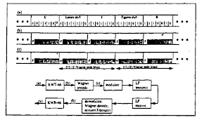
Messages use 7-bit START-STOP ITA2 (Baudot) code which is then encrypted using the KW-46 crypto equipment (KWT-46 transmitter and the KWR-46 receiver hase the code name Vallor). Encryption results in bits 1 to 6 being encrypted and bit 7 (STOP) being replaced with a deterministic unencrypted Fibonacci bit defined by the polynomial x^31+x^3+1 which provides synchronization to the receive KW-46 equipment. 
In MSK300 mode the encrypted data from KW-46 are coded into a (13,12) Wagner error coding scheme and then applied to the MSK modulator (as seen here, processing for STANAG-5065 FSK operations does not include Wagner encoding). As shown in Figure 3, the encoding includes blocking the information into 2 character groups, substituting a parity bit for every second Fibonacci bit to form a (13,12) Wagner odd parity code block (odd numbers of 1s) over 12 informations bits (Fibonacci bit excluded).
Fig. 3 - (13,12) Wagner encoding of KW-46 encrypted stream
In MSK modulations the intelligence is contained in the phase shifts and is not consistent with the frequency shifts, thus the signal can't be demodulated using a generic FSK demodulator.

Fig. 4 - MSK300 phase-plane (before equalization)
After some unsuccessful demodulation attempts I asked my friend Christoph Mayer for help, he too checked the S5065 waveform and kindly sent me an MSK demodulator written by him and re-coded for Octave. The results of the analysis of the modulated stream, shown in Fig. 5 after left shifted, perfectly matches the schema of Figure 3.

Fig. 5 -  S5065 MSK300 stream after demodulation
It's very interesting to note that both the sequence obtained with n F-bits and that obtained with n/2 (n/2 -1) F-bits are attributable to the same polynomial x^31+x^3+1, my guess is that this feature maybe helps the initial synchronization of the FEC process detecting the position of the Wagner odd parity bits.


25 November 2018

8-ary constellation bursts at 12800bps data rate (2)

Some other observations and updates about the S4539 12800bps 8-ary constellation already discussed here: this post was possible thanks to the collaboration of my friends AngazU, Christoph, Martin G8JNJ, and Sergio.

As shown in Figure 1, the polarity of mini-probes matches the 12800Ubps (6,6,2) setting so no doubt about the proper operation of the used decoders, primarily the Harris RF-5710A model.

Fig. 1a) 287 symbols preamble and sync sequence (red);
Fig. 1b) the actual "6,6,2" setting read from the preamble;
Fig. 1c) the theoretic "6,6,2" setting

Now look at the on-air symbols shown in Fig. 2: S4285 symbols (Fig. 2a) are exactly mapped to a PSK-8 constellation but the S4539 symbols being analyzed occupy different points (Figs. 2b,2c). It looks like a subset of the QAM-64 symbols is used for data  while the 4 "circled" points are the QPSK symbols of the mini-probes. Thus, since no interleaving and no coding are used in 6,6,2 mode (12800bps), the source data must be prepared such that after the scrambling the resulting 6-bit numbers will be mapped only to a 8-point subset of the QAM-64 outer ring. This makes sense and clarify the 12800bps speed, though we do not figure out why this is done.
 
Fig. 2
Figure 3 shows the plots of one frame obtained by Christoph: 256 data symbols + 31 mini-probe symbols: the 31 mini-probe symbols were descrambled and are at I=1,Q=0. As you can see the other points fit perfectly the 8 out-of-20 points of the QAM-64 outer ring [7 3 24 56 35 39 60 28].

Fig. 3 - 256 data symbols + 31 mini-probe symbols
These eight symbols have interesting structure: the 3,7,24,28 symbols are the same of  35,39,56,60 unless the left-most bit and they are at the same distance (32)

 3 000011
 7 000111
24 011000
28 011100

35 100011
39 100111
56 111000
60 111100

According to Christoph, the 6 bits are ABBCDD where ABC identify the point and D+B=1 mod 2. The ABC bits stream exhibit a 480-bit leghth period (Fig. 4).

Fig. 4
Back to the transmissions, our monitoring revealed that the entire sequence lasts about 36 seconds and consists of 6 "clusters", or "sets", each consisting of three channels with same spacing and arrangement:


Lately, our friend Martin G8JNJ noticed in the lower cluster A1 A2 A3 one weaker set (TDoA 100% St Eval) every 30 seconds (approx) and one set of stronger ones every three to five  minutes (approx) which he wasn't able to TDoA. "So that I think I'm hearing more than one transmitter site. It's proving to be very difficult to TDoA the second one, as they transmit much less frequently, but there is a big difference in RX signal strength between the transmissions", Martin says.
A friend of AngazU suggested that they could be developing some kind of turbo equalizer or similar. These emissions would be tests of a  training sequence and they would be measuring errors, convergence time and other parameters under different conditions. Just a guess, if they  succeed, we will see the  full constellation.

By the way, subjecting for example the F1 channel to the k500 decoder it prints out only 1536 decoded bits although it correctly recognizes the 12800U setting. As shown in Figure 5, each burst is made up of 13 frames for a total of 256x13=3328 QAM-64 data symbols that make 3328x6=19968 bits of data! (no interleaving neither coding is used in 12800U mode). Thus it seems that only one data frame (256 x 6) is processed by k500 (possibly the first one?): maybe it's a decoder limitation due the short burst duration? Note that it does not happen when I use the RF-5710A modem.

Fig. 5
(to be continued)

23 November 2018

WINB Red Lion to test DRM Single Channel Simulcast (SCS)

(updated)
Shortwave station WINB has recently started conducting test in DRM directed to Europe on 15670 kHz Monday - Friday from 11:00 -17:00 UTC using a new DRM 18 Kw transmitter, an ASI CE-50000WS, and Rhombic antenna at 062 degrees, according to WINB’s own website. The signal can be received by several KiwiSDR receivers in Europe, as well as by the N4LGH KiwiSDR located in Florida which has the signal from the back of the beam (Fig. 1).
My friend F4MP "Zyg" emailed me kindly asking to take a look at those "combo" test signals, given that DRM  is only located in the upper 5 KHz sideband of the channel.

Fig.1 - my reception of WINB DRM tests from N4LGH KiwiSDR

Datacast rather than simulcast? 
As from ETSI TS-102-509 V1.1.1, strictly the term simulcast can be taken to describe a transmission allowing the simultaneous transmission of analogue and digital versions of the same audio programme in one frequency channel (Single Channel Simulcast, SCS). A simulcast signal signal consists of a sinusoidal carrier and two additional signal parts in the upper and lower sideband. The digital part in the upper sideband corresponds to a DRM signal, therefore a standard DRM consumer receiver will be able to extract and decode the included digital data. An analogue audio AM receiver applying envelope demodulation on the overall received signal will provide an audio signal to the listener comparable to standard AM transmission. [1] [2]
Clearly, that's not the case of WINB. Moreover, due to the fact that multipath propagation via the ionosphere is a typical characteristic of radio channels in HF broadcasting, the use of SCS is recommended only for LF and MF bands with mainly ground wave propagation.

So, what is carried by the lower sideband of the signal?
Nobody knows with certainty, at least at present when I'm writing this post. Interesting discussions on WINB DRM test transmissions can be read in the DRM Forum as well as in w4uvh site:
Oddly, on DRM Forum nobody associated with WINB has commented on the simul/datacasting although they have made several posts regarding the DRM broadcast.
 
Looking at FCC license for these tests we note the 10K00G9W emissions designator for the CE-50000WS transmitter beamed to north Europe (Fig. 2):

Fig. 2 - FCC license
10K00G9W designator means that WINB may transmit:
10 k = 10 kHz signal bandwidth
G = phase modulation
9 = Analog and digital channels
W = any combination of telegraphy, fax, data, telephony or video

so the license offers the chance to transmit digital signals or ordinary AM signals.
Analyzing the lower sideband of the signal I may count up to 78 unmodulated tones that could be MFSK as well as constructed using OFDM tecnology, in this case the tones have rotated phases. Likely it's a test/experimental transmission w/out data carried.
Fig. 3
Fig. 4
31 October update
I have a little but important update: some days ago I heard WINB DRM signal at my QTH on 13690 KHz, surely due to good propagation conditions. I twitted a little post and WINB answered asking a report about that reception. The most important fact is that they confirmed data transmission o the lower 5 KHz channel.


23 November update
First time, at least at my side, that I hear their emissions on 9265.0 KHz in the morning: a bit unusual band (30mt) since the time (0930 UTC). Maybe they are testing the "service" in different bands?