31 May 2017

3G link + S5066: example of Circuit Mode (HF2000, Swedish Defence)

Nice example of how to send STANAG-5066 data on a 3G link, using the Circuit Mode service provided by the 3G-HF STANAG-4538 profile.The link is established with the 1-way FLSU procedure then 188-110A Serial at 1200 bps is used for the data transfer. After the transfer is completed, an FLSU_Term PDU is sent by the caller and the link is terminated (Fig. 1).

Fig. 1
The most interesting aspect is the use of STANAG-5066, which has been detected thanks to the lack of the encryption before the MS110 modem: indeed, STANAG-5066 allows to indentify the Authority/Country by the addresses coded into the Data PDU (D_PDU), unless dummy addresses are used:

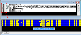
Once removed the overhead bits added by MS110, the D_PDUs can be isolated by syncing the resulting bitstream with the sequence 0xEB90 (regardless of type, all the D_PDUs begin with the same sync sequence): the result is displayed in Figure 2.

Fig. 2
The Size-of-Address Field specifies the number of bytes in which the source and destination address are encoded, the address field may be from 1 to 7 bytes in length (as in this case), with the source and destination address of equal length.The first half is the destination address and the second half is the source address:

In this case:
source address: 006.046.000.028
destination address: 006.046.001.010
both belonging to the block 6.46.x.y allocated to Sweden (Table N-6 European National Addressing Schema):

Fig. 3
 

26 May 2017

FSK 100Bd/620, Polish Intel


FSK-2 modulation with 620 Hz shift and 100 Baud speed, in use by Polish Intel service.

pic. 1 - baudrate and shift
The signal exhibits clean ACF spikes at 96 bits (~960ms lenght). Looking more closely one can distinguish six periods of 16 bits, most likely they represent a five digits code and a separator between the groups as also shown in the bitstream (pic. 3).

pic. 2 - 96 bits ACF (6 x 16 bits digits)
.
pic. 3
Looking at the whole demodulated bitstream (pic. 4), although inclusive of the overhead bits, we can get an idea of the signal structure. First of all, note that the ACF is due to the final part "D" and then does not characterize the entire signal but only a part. While the parts A and E can be assumed as the 'start' and 'end' of transmission, it's difficult to fix the roles of the other groups: message, destination address, coded-instructions and so on. Talking with my friend KarapuZ, he says we need much more recordings for statistic comparisons since a previous recording of 2014 just exhibits that same characteristics. And if he says so...

pic. 4
May,26 2017 udate

This morning I copied a transmission on 10211.6 KHz/USB with same ACF (96 bit) but with different frame structure that exhibits a sort of 24-bit length "preamble" followed  by 16-bit length data blocks (8+8 UK) and resembling, in some way, the Stanag/MIL-STD framing.


https://yadi.sk/d/jJ_1leZR3JYWKW


April,23 2019 udate
Another waveform used by Polish Intel is QPSK 100Bd, mostly used on 7318.0 KHz (cf). The demodulated bistream shows a 16-bit period.


https://yadi.sk/d/AcAqiHySmAuCCg

24 May 2017

Doppler spread monitoring in 9 MHz band signals


Looking for "Spectan" software download I come across an interesting  web page  about the "Precision Carrier Doppler Analysis": intrigued by this argument, I tried to replicate the Doppler spread analysys and these are the results of my one-day monitoring of two transmissions in the 9 MHz band (9182.0 and 9115.0 KHz, both in USB).

Due to the time-varying nature of the ionosphere, the propagation path is never static and the received sky-wave signals may suffer distortion in the form of temporal dispersion (delay spread) as well as fluctuation in the signal’s amplitude and phase (Doppler spreading). Recent high latitude measurements have observed multipath signals of more than 10 ms duration and other signals have shown evidence of Doppler spreading greater than 50 Hz. More typical mid-latitude sky-wave channels might show delay spreads of 1 - 4 ms with Doppler spreads of 1 Hz or less.
In a few words, Doppler spread occur because during the day the apparent height at which signals are reflected changes quite markedly, leading to quite easily observable frequency shifts. It is the rate of change of apparent height which is related to the frequency shift. Doppler spread  is commonly defined as the range of frequencies over which the received Doppler spectrum is essentially non-zero. When a pure sinusoidal tone of frequency fc  is transmitted, the received signal spectrum will have components in the range fc – fd to fc + fd , where fd is the Doppler shift. 

Looking for suitable transmissions to monitor, I decided in favor of the continuous B'casts of the Russian Navy on 9 MHz band: such transmissions are on USB and use the AT-3004D modem known as CIS-12. The signal consists of 12 BPSK modulated tones (MPSK), 120 bps per channel, with a Pilot Tone at ~3300 Hz which is just used for Doppler correction at receiving sites.

1) daylight path, 9182.0 KHz CIS-12 transmission (Fig. 1)

Fig. 1
During the daylight path the  the Doppler spread is less than 1 Hz (as expected), since during the day the D layer supposedly absorbs the signal before it reaches the ionosphere. However, the absorbtion is not always complete, and the signal is also propagted via its E-layer daytime reflection. The E layer is relatively stable, and shows little Doppler spread (Fig. 2).
Starting from about 1630 UTC (Fig. 3), the region of the transmitter enters in its Grey Line and the signal starts to be seen from various scatter paths and then reflected from the F-layer. The rise of the Doppler spread is quite easily observable.

Fig. 2
Fig. 3
 
2) darkness path (after local sunset), 9115.0 KHz CIS-12 transmission (Fig. 4)
 
Fig. 4
Starting from about 17.30-1800 UTC (summer time, in my area) the D layer stops absorbing completely, and the signal starts to be reflected from the F-layer. At this time the effective height of the F layer is rising as ion density decreases and the Doppler spread reflects the instability of the F layer. I do not know the reason of the drift around 20.00 UTC.

Fig. 5
Fig. 6
It's interesting to see that the two transmissions have Doppler tones which differ of about 10 Hz: most likely it is due to two different transmitters.

3) setup
As said, the software used for this monitoring is "Spectran" - Current version : Version 2 build 216 - and it can be downloaded from http://www.weaksignals.com/
Spectran is a spectrum analyzer written by Alberto, I2PHD and Vittorio, IK2CZL, members of the PAcket Digital Amateur Network group (PADAN), who created also other weak signal and QRSS programs. Spectran allows real time or deferred spectral analysis / waterfall display, in addition to real time audio filtering (band pass, denoising, band reject and CW peaking) of audio signals, using the PC sound card to digitize the input analog signal, or taking as input a WAV file. Its characteristics are well suited to dig weak signals buried into noise, thanks to a selectable bin size down to 21 millihertz.

The "Doppler mode" settings that I used for this monitoring are shown in Figure 7:

Fig. 7
And... yes, It would be much more interesting to monitor the same transmission for more than one day and in different seasons, but this is not my job :)

17 May 2017

RACAL MA4248 "MEROD", ARQ FSK 266.6Bd/800Hz


The transmission was heard on 9274.0 (cf) and consists of FSK-2 bursts with shift of 800Hz and manipulation speed of 266.67 Baud. Thes features points at the RACAL MA4248 device, also known as MEROD (Message Entry Read Out Device): thanks to my friend KarapuZ for the help in identification.

Fig. 1 - manipulation speed
Fig. 2 - FSK shift
Once demodulated the signal, the measured period is 48 bits:

Fig. 3 - 48-bit period
The RACAL MEROD transmissions can be decoded by Code-300, although the contents are encrypted: 

Fig. 4 - MEROD RAC-ARQ mode running in Code-300

The RACAL MA4248 "MEROD" device was  designed for sending messages in burst transmission mode over HF/VHF/UHF radio links and were therefore used by special forces in combination with a man pack radio, these unit is also known as a tactical data entry device, TDED. MA4248 utilise a complex error correction system that ensures that the message can be correctly received over very poor quality HF links.

Fig. 5 - RACAL MA4248 device


10 May 2017

CIS-40.5 (CIS-81-81, T-206)

CIS-40.5 FSK (T-206 chiper devices family) is the single channel version of CIS-81. It's a quite "old" mil system, most likely in use by some ex USSR republic.
So far, I had CIS-40.5 in three different waveforms:

40.5Bd 120 (supposedly)
Traffic is encrypted and the demodulated stream at my disposal doesn't offer any information. Other samples are needed for further analysis.

Fig. 1
Fig. 2 - CIS-40.5 120Hz shift demodulated shift

40.5Bd 250
It's the most interesting waveform since its demodulated stream exhibits a 12-bit format due to the idle signal (6 mark and 6 space bits). The scrambler x^11+x^9+1 is superimposed to the data block transmitted between idles (Fig. 5). Data blocks are encrypted and consist of 6-bit frames.

Fig. 3
Fig. 4
Fig. 5

40.5Bd 500
Unfortunately the recording at my disposal onsly consists of reversals so it doesn't offer any useful information unless the match of the FSK values (speed and shft). As above, other samples are needed for further analysis.
 
Fig. 6
 
https://yadi.sk/d/UTty-5kNJO7b7w (120Hz shift)
https://yadi.sk/d/LYyCXmiP9EQCcQ (250Hz shift)
https://yadi.sk/d/adyKaXEkwL8FdA (500Hz shift)

8 May 2017

interesting paper about IP Multicasting in HF Radio Networks

I recently found in the web the interesting paper titled IP Multicasting in HF Radio Networks (2008) that proposes a multicast data link protocol for third generation (3G) high frequency (HF) radio networks:
http://mac-ee211.nmsu.edu/hf/papers/3g_mdl.pdf
I have a doubt about the "MDL Operation" paragraph and the related Figure 3 of the paper:


According to §4.6.5 "Dual Demodulation" of Annex-C to STANAG-4538 Ed.1: under no circumstances shall PUs be required to simultaneously demodulate more than two waveforms.
Well, at time "tn" in Figure 3 the receiving PUs expect an LDL_DATA PDU (BW3) or an LDL_EOM/TERM PDU (BW4): sending a FLSU PDU (BW5) would impose a triple demodulation requirement. 

Thus, the calling PU shall send an LDL_EOM PDU (BW4) to indicate that the entire datagram has been transferred and the FEC Phase 0 session is terminated; then the following FSL PDU (BW5) will be sent to announce the repetition of the datagram in the alternate FEC code:

Anyway, since the multicast scenarios proposed in the paper have been evaluated using the DoD-validated HF Network Simulator (NetSim-SC), and then not implemented in real radios, the procedure depicted in Figure 3, although wrong, could be a simplification.


6 May 2017

NATO "copy-and-paste" ...and errors

Computer-based editing can involve very frequent use of copy-and-paste operations but sometimes these operations can lead to significant errors. I came across a case by reading the Annex C to STANAG-4538 Ed.1, more precisely the Amendment 21. The problem arises in "TABLE 7.2.5.2-1. LDL actions", where is specified (litterally):
"Note: The LDL transmitter can send duplicate packets either as a result of missing an LDL_ACK PDU, or at the end of a datagram, in order to fill the (otherwise unused) packet positions of an LDL_DATA PDU. The LDL receiver is required to inspect the sequence number of each data packet received without errors, and to use the sequence numbers to identify and discard duplicate packets." (highlighted in Figure 1).
Fig. 1
This text is clearly a copy-and-paste from "TABLE 7.1.5.2-2. HDL actions", unless the the term HDL (Figure 2):
Fig. 2

Well, the statement "The LDL transmitter can send duplicate packets either [...] or at the end of a datagram, in order to fill the (otherwise unused) packet positions of an LDL_DATA PDU."  (Fig .1) is wrong since LDL protocol, contrary to HDL, does not provide 'packet positions' in its DATA PDU but rather one single packet at a time! (each HDL_DATA PDU is a sequence of 24, 12, 6, or 3 data packets, in which each packet is composed of 233 bytes of payload data; each LDL_DATA PDU is a single data packet composed of 32, 64, 96,..., 512 bytes of payload data).

It's an oversight that hopefully will be edited in the next edition :)

5 May 2017

STANAG-4538 HDL+, BW7 QAM-16 waveform


- Burst Waveform 6 (BW6) is used to convey the HDLP_DHDR, HDLP_ACK, and HDLP_EOT PDUs of the HDL+ data link protocol, and to convey PDUs of the FLSU and FTM protocols on a packet link established for delivery of data traffic using HDL+ (note the Link terminate PDU that is conveyed by a BW6 burst). BW6 PDUs bursts have 51 bits of payload, an on-air duration of 386.67 ms, and are transmitted using a PSK-8 modulation.
- Burst Waveform 7 (BW7) is used for transfers of traffic data by the HDL+ protocol. The HDL+ protocol combines high data rate waveforms similar to those of MIL-STD-188-110C Appendix D with incremental redundancy techniques. 

Given the variable lengths and modulation formats of HDL+ data, it's necessary to include a header at the beginning of each BW7 PDU (which was unnecessary in LDL and HDL) that announces the number of packets and modulation format of the following payload section of the transmission (HDLP_Data PDU). For this header, the HDL+ uses a BW6 PDU (HDLP_DHDR PDU). 
Since BW6 symbols are modulated using a PSK-8 constellation, the structure composed of BW6-BW7 PDUs
will be clearly visible in those cases where BW7 use a different constellation for its symbols, such as QAM-16 or QAM-64 (BPSK and QPSK are scrambled to appear on-air as a PSK-8 constellation). 
Just yesterday, I copied a such HDL+ data transfer on 11132.0 KHz/USB. As displayed in Figure 1, the 8th power harmonics are present for all the duration of the BW5 and BW6bursts, but only in the initial segments of the BW7 bursts, ie in the BW6 PDUs that work as headers. The HDLP_DATA PDUs are instead modulated using a QAM-16 constellation (12 points in the outer ring, 4 in the inner ring).


Fig. 1

For what concerns the analysis of the BW7 waveform, no initial synchronization preamble is required since this role is filled by the BW6 HDLP_DHDR PDU. Instead, an initial probe sequence containing two repetitions of a 32-symbol Frank-Heimiller sequence (a total of 64 known symbols) is transmitted.
The following section is used to convey between one and fifteen (inclusive) packets. Each packet is composed of a sequence of unknown/known (“UK”) frames. Each UK frame contains a data block, a sequence of 256 unknown symbols modulated with payload data, followed by a 32-symbol mini-probe. The number of UK frames used to convey each data packet depends on the signal constellation, the code rate, and the payload size.

Fig. 2
Fig. 3
 
Other than the recording of the transmission, a short video (from my YouTube channel) that illutrates the analysis with SA  is also available.


https://youtu.be/rRI-kgf_b9Y


3 May 2017

STANAG-5066, ARQ & non-ARQ PDUs in a real-world HF radio link

The STANAG-5066 standard, and its second generation Data Link Protocol, provides data transfer using ARQ as well as non-ARQ point-to-point, broadcast or multicast data transfer. The Data Transfer Sublayer (DTS) is responsible for the efficient data transfer across the radio link and use the D_PDU types displayed in Figure 1 to support both ARQ and Non-ARQ services:

Fig. 1 - D_PDU types used by STANAG-5066 DTS
For what concerns the I-frame D_PDUs: 

- the NRQ (No Repeat-Request or non-ARQ) Protocol, commonly known as broadcast mode, only operates in a simplex mode since the local node, after sending I-frames, does not wait for an indication from the remote node as to whether or not the I-frames were correctly received. Multiple repetitions of I-frames can be transmitted in order to increase the likelihood of reception under poor channel conditions, in accordance with the requested service characteristics.

- the SRQ (Selective Repeat-Request) Protocol operates in a half or full duplex mode since the local node, after sending I-frames, waits for an indication in the form of a selective acknowledgement from the remote node as to whether the I-frames were correctly received or not. The local node then either sends the next I-frames, if all the previous I-frames were correctly received, or retransmits copies of the previous I-frames that were not. The local node will retransmit copies of the previous I-frames if no indication is received after a predetermined time interval.

Pinpointing D_PDUs in a real-world HF radio link is not difficult since, regardless of type, they all begin with the same Maury-Styles 16-bit sync sequence 0xEB90, with the least significant bit (LSB) transmitted first
 (MSB) 1 1 1 0 1 0 1 1 1 0 0 1 0 0 0 0 (LSB)
The D_PDU type field occupies the 4 most significant bits of the 3rd byte (Figure 2).

Fig. 2 - Generic D_PDU Frame Structure
The chosen example is a S-5066 data transfer that uses MIL 188-110A Serial as HF waveform (Fig. 3):


Fig. 3- 188-110A over-the-air symbols
Once removed the overhead bits added by 188-110A, the D_PDUs can be isolated by syncing the resulting bitstream with the sequence 0xEB90 (the DS_PDU SYNC sequence): the result is displayed in Figure 4.

Fig. 4
 
The NON-ARQ DATA (type 7) and EXPEDITED NON-ARQ DATA (type 8) D_PDUs are used to send segmented data when the transmitting node needs no explicit confirmation the data was received (NRQ mode).

Fig. 5 - type 8 D_PDU
 
The DATA-ONLY (type 0) D_PDU is used to send segmented data when the transmitting node needs an explicit confirmation the data was received. The DATA-ONLY D_PDU is used in conjunction with a basic selective automatic repeat request type of protocol.

Fig. 6 - type 0 D_PDU

The ACK-ONLY (type 1) D_PDU is used to selectively acknowledge received DATAONLY or DATA-ACK D_PDUs when the receiving station has no segmented C_PDUs of its own to send.

Fig. 7 - type 1 D_PDU

As indicated in Figure 2, the header of every D_PDU includes an end-of-transmission (EOT) field. This 8-bit field specifies how much of the current transmission remains, in units of one-half second. This elegantly eliminates the end-of-transmission ambiguity that arises during an extended channel fade. If even a single header is received error-free, the receiver knows when it will be safe to send an ACK. Note that this field bounds the duration of STANAG 5066 transmissions at just over two minutes. This field is also used in case of non-ARQ (type 8) D_PDUS, as displayed in Figure 8

Fig. 8 - the (decreasing value) EOT field

Note:
in some cases, the shown results could suffer of the lack of error-frames which have not been correctly demodulated or discarded.